4
Parameter Settings for Regulation Mode:
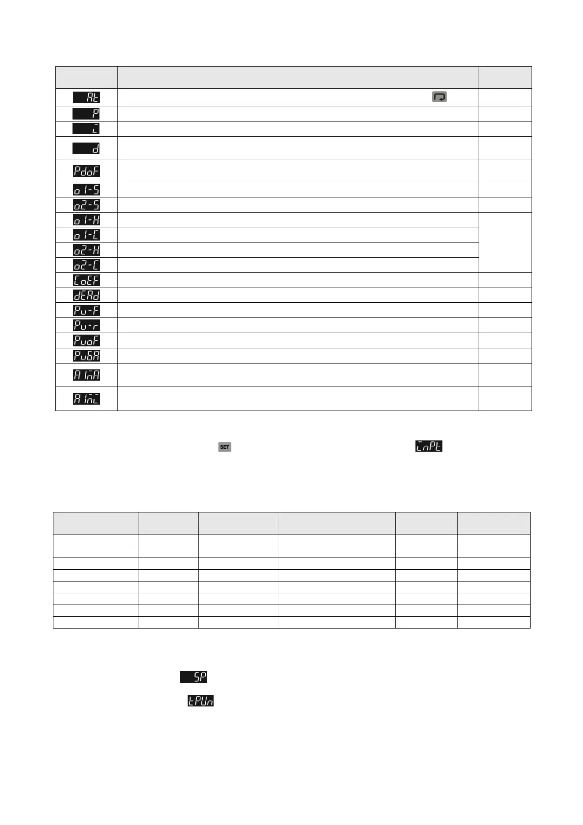
Display Description
Factory
Setting
AT: Auto-tuning Switch (display when setting Ctrl = PID/RUN) Press
.
OFF
P: Proportional Setting (display when setting Ctrl = PID and TUNE = AT)
47.6
I: Integral Time Setting (display when Crtl = PID; this parameter is set automatically when TUNE = AT.)
260
D: Deviation Time Setting
(display when Crtl = PID; this parameter is set automatically when TUNE = AT.)
41
PD OFFSET: PD offset when Integral = 0 to eliminate a consistent deviation.(display when Crtl = PID;
this parameter is set automatically when TUNE = AT.)
50.0
OUT1 HYSTERESIS: Adjust Output 1 hysteresis (when in ON/OFF control)
0
OUT2 HYSTERESIS: Adjust Output 2 hysteresis (when in ON/OFF control)
0
OUT1 HEAT: Heating control cycle for Output 1 (when Ctrl = PID/MANUAL)
Output
selection:
C; V: 5 sec.
R output
20 seconds
OUT1 COOL: Cooling control cycle for Output 1 (when Ctrl = PID/MANUAL)
OUT2 HEAT: Heating control cycle for Output 2 (when Ctrl = PID/MANUAL)
OUT2 COOL: Cooling control cycle for Output 2 (when Ctrl = PID/MANUAL)
COEF: Ratio of Output 1 against Output 2 (when Ctrl = PID and when in dual output control)
1.00
DEAD: Set up deadband (when Ctrl is not set to MANUAL and when in dual output)
0
PV FILTER: Set up input filter factor of PV
2
PV RANGE: Set up input filter range of PV
1.00
PV OFFSET: Adjust input compensation of PV
0.0
PV GAIN: Adjust input gain of PV
0.000
ANALOG OUT1 MAX.: Adjust upper limit compensation for analog Output 1
(1 scale = 1 μA; 1 scale = 1 mV)
0
ANALOG OUT1 MIN.: Adjust lower limit compensation for analog Output 1
(1 scale = 1 μA; 1 scale = 1 mV)
0
Initial Start-up Setting
When setting up DTK for the first time, press key for more than 3 seconds till the screen display and select according to
your temperature sensor type. Please be aware that incorrect selection of a model would cause PV temperature display error. (Refer to
the chart below)
When setting up the temperature sensor type by using RS-485, write your value (range 0~14) into register 1004H.
Temperature Sensor Type & Temperature Range Chart
Input Temperature
Sensor Type
Register Value Temperature Range Input Temperature Sensor Type Register Value Temperature Range
Thermocouple K type 0 -200 ~ 1300°C Thermocouple L type 8 -200 ~ 850°C
Thermocouple J type 1 -100 ~ 1200°C Thermocouple U type 9 -200 ~ 500°C
Thermocouple T type 2 -200 ~ 400°C Thermocouple TXK type 10 -200 ~ 800°C
Thermocouple E type 3 0 ~ 600°C Platinum Resistance (JPt100) 11 -100 ~ 400°C
Thermocouple N type 4 -200 ~ 1300°C Platinum Resistance (Pt100) 12 -200 ~ 850°C
Thermocouple R type 5 0 ~ 1700°C Resistance (Ni120) 13 -80 ~ 300°C
Thermocouple S type 6 0 ~ 1700°C Resistance (Cu50) 14 -50 ~ 150°C
Thermocouple B type 7 100 ~ 1800°C
Display Unit Setting
Use following parameter to change the PV and SV display unit, select decimal point and switch between Ԩ/Ԭ.
In Operation Mode
parameter : SP = 1 displays decimal place (ex: 25.5 degree); SP = 0 displays integral number (ex: 25
degree).
In Initial Setting Mode
parameter : Select temperature display unit Ԩ/Ԭ. (Ԭ=Ԩ* 9 / 5 + 32)
 Loading...


