11
(word/bit)
02H 09H
data
1000H/081xH
F4H 01H 20H 00H 20H 00H
CRC 1 C0H BBH
Address data
1001H
03H CRC 1 DDH 8FH CRC 1 DDH 8FH
CRC 0 CBH A9H 20H CRC 0 E2H 9FH CRC 0 E2H 9FH
CRC 1 BBH 77H
CRC 0 15H 88H
CRC check code: CRC (Cyclical Redundancy Check) is obtained via the following steps.
1. Load in a 16-bit register FFFFH as the CRC register.
2. Perform an exclusive OR operation for the first byte of the data and low byte of CRC register. Place the operation result back to
the CRC register.
3. Right-shift the bits in the CRC register and fill the high bits with “0”. Check the lowest bit removed.
4. If the removed lowest bit is “0”, repeat step 3. Otherwise, perform an exclusive OR operation for the CRC register and the value
of A001H. Place the operation result back to the CRC register.
5. Repeat step 3 and 4 until the 8 bits (1 byte) are all right-shifted.
6. Repeat step 2 and 5 and calculate all the bits in the data to obtain CRC check code.
Please be aware of order of transmission for the high/low bytes in the CRC register.
Panel Cutout
Model Panel Cutout (W * H) Model Panel Cutout (W * H)
4848 45mm * 45mm 7272 68mm * 68mm
4896 44.5mm * 91.5mm 9696 91.5mm * 91.5mm
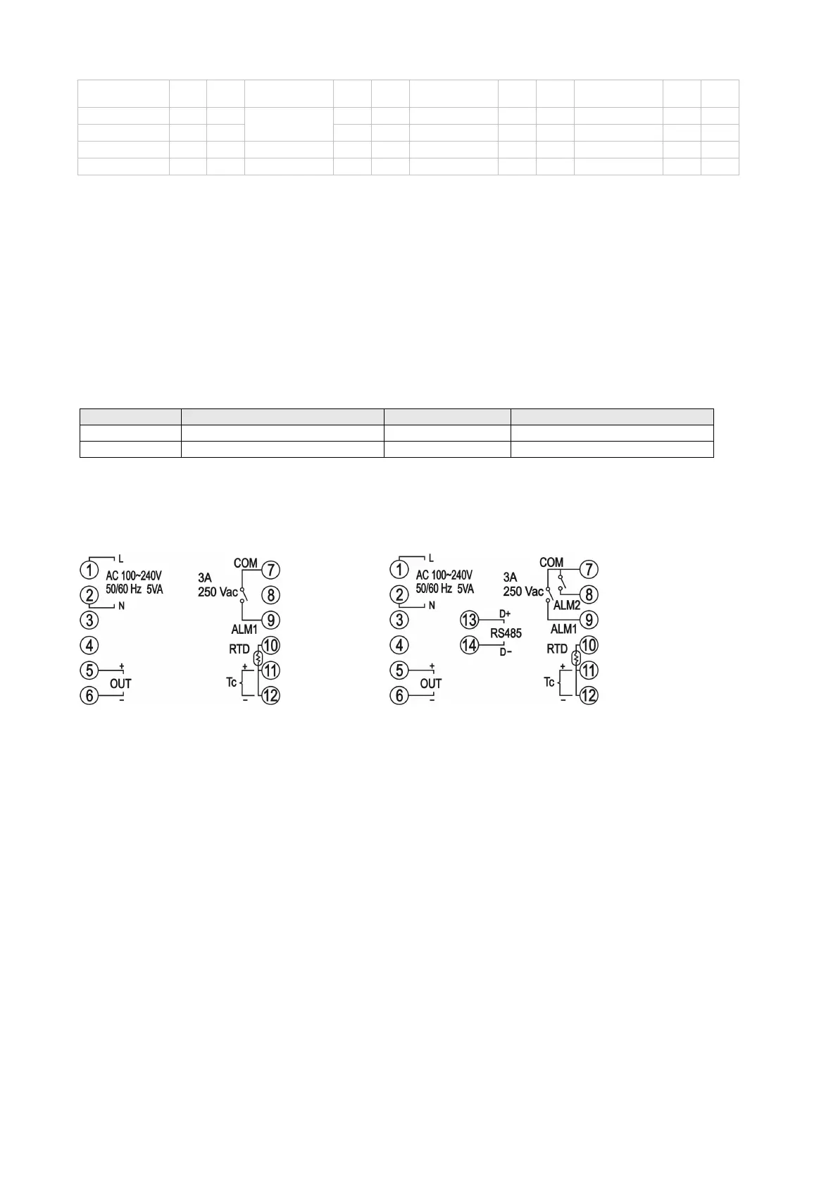
Wiring Diagram
4848 Series:
(1 set of alarm output) (2 sets of alarm outputs or with RS485 communication)
 Loading...


