EasyManua.ls Logo

Delta DTI Series - User Manual

Delta DTI Series
10 pages
To Next Page IconTo Next Page
Loading...
1
2019/08/12
Series Temperature Controller Instruction Sheet
Precaution
Warning! Please comply with safety precautions in the manual. Failure to do so may cause controller or peripheral products
malfunction, or even result in serious harm such as fire, electrical injury or other damages.
DANGER! Caution! Electric Shock! Do not touch the AC terminals while the power is supplied to the controller to prevent electric
shock. Make sure power is disconnected while checking the unit inside.
This controller is an open-type temperature controller. Be sure to evaluate any dangerous application in which a serious human
injury or serious property damage may occur.
This controller is not furnished with a power switch or fuse, therefore a switch or circuit-breaker should be provided in the
application system including this unit. The switch or circuit-breaker should be nearby and easily reached by operator, and must
have the mark disconnecting means for this unit.
1. Always use recommended solder-less terminals: Fork terminal with isolation (M3 screw, width is 5.8 mm). Make sure all wires are
connected to the correct polarity of terminals.
2. Do not allow dust or foreign objects to fall inside the controller to prevent it from malfunctioning. Never modify or disassemble the
controller. Do not connect anything to the "No used" terminals.
3. To prevent interference, keep away from high voltage and high frequency when installing. Do not install and/or use the controller in
places subject to:
(a) Dust or corrosive gases and liquid; (b) High humidity and high radiation; (c) Vibration and shock;
4. Power must be off when wiring and replacing a temperature sensor.
5. Be sure to use compensating wires that match the thermocouple types when extending or connecting the thermocouple wires.
6. Please use wires with resistance when extending or connecting a platinum resistance thermometer (RTD).
7. Please keep the wire as short as possible when wiring a platinum resistance thermometer (RTD) to the controller and please route
power wires as far as possible from load wires to prevent interference and induced noise.
8. This controller is an open-type unit and must be placed in an enclosure away from high temperature, humidity, dripping water,
corrosive materials, airborne dust, and electric shock or vibration.
9. Make sure power cables and signals from instruments are all installed properly before energizing the controller, otherwise serious
damage may occur.
10. Do not touch the terminals in the controller or try to repair the controller when power is on, in order to prevent electric shock.
11. Wait at least one minute after power is disconnected to allow capacitors to discharge, and please do not touch any internal circuit
within this period.
12. When maintaining the controller, please turn off the power first and use a dry cloth to clean the surface. Do not open the enclosure or
touch the internal circuit to avoid circuit destruction or malfunction.
13. Do not use any sharp objects to press the operation buttons. It may result in button surface damage or even electrical injury when
accidentally access to internal circuit.
14. Use copper conductors only.
Product Features
DTI series is a new temperature controller with a high cost-performance ratio. It greatly decreases development costs and time, and
improves the functions of temperature control systems. With a length of only 60mm and high resolution LCD display, it is easy for
operators to monitor the temperatures of any environment or occasion.
High resolution LCD panel: High contrast and customized display graphics for user’s easy understanding.
High-speed sampling time 100ms: High-speed sampling for external temperature measurement and fast output response for
performance requirements of high-precision control.
Shortened length to 60mm: Shorten the length of the controller to reduce the installation space.
Conform with CE international safety certification
Question and Answer IconNeed help?

Do you have a question about the Delta DTI Series and is the answer not in the manual?

Delta DTI Series Specifications

General IconGeneral
Control AlgorithmPID, Auto-tuning
SeriesDTI
Control ModePID, On-Off
InputThermocouple, RTD
OutputRelay
DisplayLED
Power Supply24V DC, 100-240V AC
CommunicationRS-485
Dimensions96x96mm

Summary

Precaution

General Safety Warnings

General safety warning for the controller and connected peripherals to prevent harm.

Electric Shock Hazard

Warning against touching AC terminals while power is supplied to prevent electric shock.

Open-Type Controller Application

Evaluate dangerous applications where serious injury or property damage may occur.

External Power Control Requirement

The controller requires an external switch or circuit-breaker for safety and operation.

Wiring and Installation Guidelines

Instructions on using solder-less terminals, preventing dust, avoiding interference, and proper wiring.

Product Features

High Resolution LCD Display

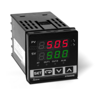
Features a high contrast LCD panel for easy monitoring and understanding.

High-Speed Sampling

100ms sampling time for fast external temperature measurement and response.

Compact Size

Shortened length of 60mm reduces installation space.

CE Certification

Conforms with CE international safety certification standards.

Basic System Structure

System Operation Overview

Explains how the controller measures temperature, processes data, and controls heating via outputs.

Display, LED & Pushbuttons

Interface Elements

Describes the PV/SV display, LEDs (Celsius/Fahrenheit, Alarm, Mode), and pushbutton functions.

Ordering Information

Model Selection Guide

Details series, panel size, output options, and communication options for ordering.

Specifications

Electrical and Input Specifications

Covers input voltage, power consumption, display method, sensor types, control modes, and output types.

Environmental and Physical Specs

Details alarm output type, display accuracy, sampling rate, vibration, shock, ambient temp, altitude, and humidity.

Operation Modes and Settings

Operation Modes Overview

Explains the three modes: Operation, Regulation, and Initial Setting, and how to switch between them.

Parameter Settings for Operation Mode

Lists parameters adjustable in Operation Mode, like RUN/STOP, decimal point, and alarm settings.

Parameter Settings for Initial Setting Mode

Lists parameters for initial setup, including input type, temperature unit, and limits.

Alarm Output Configuration

Alarm Settings and Modes

Details the 9 alarm modes, including deviation, absolute value, and hysteresis alarms.

Alarm Parameter Configuration

Explains how to set alarm delay, reverse, standby, and hold parameters.

Display Unit Setting

How to change the PV and SV display unit to Celsius or Fahrenheit and set decimal points.

Input Value Adjustment

Set Value and Input Limits

Setting the Set Value (SV) and configuring upper/lower input limits.

Digital Filter and Linear Compensation

Adjusting filter factors and linear compensation for signal stability and accuracy.

Firmware and Output Type Check

How to check firmware version, output type, and input type during startup.

HeatingCoolingAlarmDual-Loop Control

Selecting and configuring control modes for heating, cooling, or alarm outputs.

Control Mode Settings

ON-OFF Control Mode

Describes the ON-OFF control logic for heating/cooling with adjustment sensitivity and dead band.

PID Control Mode

Explains PID operation, parameter setting, auto-tuning, and dual output control with Coef and DeadBand.

Advanced Settings and Functions

Auto-Tuning (AT) Function

How to perform auto-tuning to automatically generate PID parameters for optimal control.

Output Range Limits

Setting maximum and minimum limits for control output percentages.

Temperature Range Limits

Configuring upper and lower limits for the input temperature range.

Factory Settings Restore

Procedure to restore the controller to its factory default settings.

Key Lock Functionality

How to lock/unlock the keypad and change the password.

Alarm Output Details

Alarm Function Disabled

Setting for disabling alarm functions.

Deviation Alarms

Types 1-3 for deviation alarms based on PV relative to SV.

Absolute Value Alarms

Types 4-6 for alarms based on absolute PV values against limits.

Hysteresis Alarms

Types 7-8 for hysteresis alarms with ON/OFF switching points.

Disconnection Alarm

Type 9 for detecting sensor disconnection or incorrect connection.

Alarm Mode and Parameter Settings

How to set alarm mode, deviation limits, delay, reverse, standby, and hold.

Error Codes and Installation

Error Code Interpretation

Explains panel error codes like 'no', 'cont', 'SEn', 'Err' for sensor issues.

Panel Cutout Dimensions

Provides panel cutout dimensions for 4848 and 9696 series controllers.

Mounting and Bracket Installation

Step-by-step guide for installing the controller using mounting brackets for 4848 and 9696 series.

Wiring and Service

Wiring Diagrams and Precautions

Illustrates wiring diagrams for 4848 and 9696 series and provides wiring precautions.

Product Service Information

Information on where to find more temperature controller details and technical support.

Related product manuals