unlocked. If two entries of the password are not the same, the screen will return to the state of step 2.
Cannot remember the password:
Restore factory settings to release the locking.
Alarm Outputs
This controller features one or two alarm outputs. A total of 9 alarm settings can be made independently as shown in the table. Additional
settings are provided, such as alarm delay, alarm standby, alarm output hold, and alarm reverse output, as described below:
Alarm Delay Setting: Sets alarm delay time. When action conforms to the alarm setting mode, controller will delay generation of an alarm
signal. An alarm will only be activated when the alarm conditions remains confirmed within the delayed period of time.
a. Alarm Standby Setting: An alarm detection will only be activated when the measured value falls within ±5 range of specified input
value, so as to prevent an alarm activation on start-up if the condition conforms to the alarm setting.
b. Alarm Output Hold Setting: The alarm message will be held when the alarm is activated, unless it is switched off on the alarm.
c. Alarm Reverse Output Setting: An alarm output can be set for NC (Normal close) or NO (Normal open).
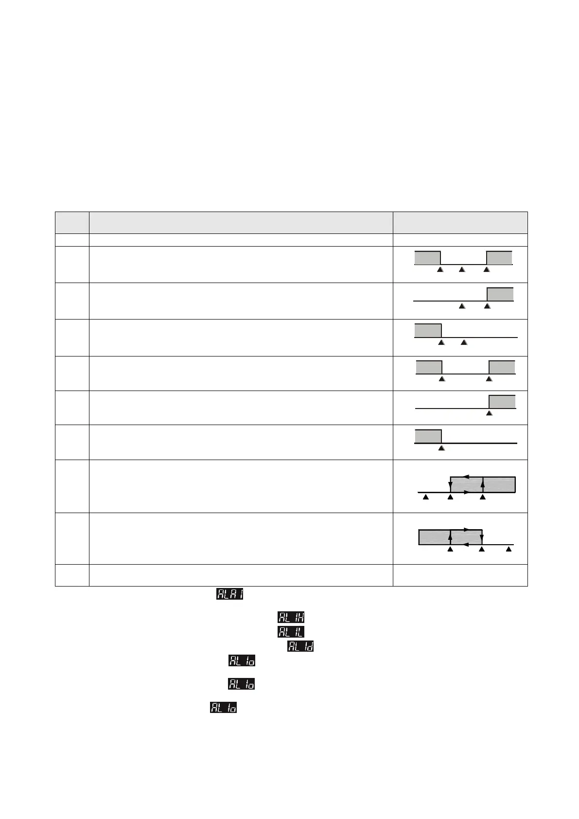
Deviation upper- and lower-limit: This alarm output operates when PV value is higher
than the setting value SV+(AL-H) or lower than the setting value SV-(AL-L).
ON
OFF
SV-(AL-L)
SV
SV+(AL-H)
Deviation upper limit: This alarm output operates when PV value is higher than the
setting value SV+(AL-H).
Deviation lower limit: This alarm output operates when PV value is lower than the
setting value SV-(AL-L).
Absolute value upper and lower limit: This alarm output operates when PV value is
higher than the setting value AL-H or lower than the setting value AL-L.
Absolute value upper limit: This alarm output operates when PV value is higher than
the setting value AL-H.
Absolute value lower limit: This alarm output operates when PV value is lower than the
setting value AL-L.
Hysteresis upper limit alarm output: This alarm output operates when PV value is
higher than the setting value SV+(AL-H). This alarm output is OFF when PV value is
lower than the setting value SV+(AL-L).
ON
OFF
SV SV+(AL-L) SV+(AL-H)
Hysteresis lower limit alarm output: This alarm output operates when PV value is
lower than the setting value SV-(AL-H). This alarm output is OFF when PV value is
higher than the setting value SV-(AL-L).
ON
OFF
SV-(AL-H) SV-(AL-L) SV
Disconnection Alarm: This alarm output operates if the sensor connection is incorrect
or has been disconnected.
To set Alarm Mode: Use the parameters in Initial Setting Mode to select the alarm mode. There are 9 different modes (as
shown in the table above).
To set Deviation Upper Limit of Alarm: Use the parameters in Operation Mode to set the deviation upper limit.
To set Deviation Lower Limit of Alarm: Use the parameters in Operation Mode to set the deviation lower limit.
To set Alarm Delay Time (Unit: seconds): Use the parameters in Initial Setting Mode to set the alarm delay time.
To set Reverse Alarm: Use the parameters in Initial Setting Mode to set value of the corresponding position Y in xxYx
(when Y = 0: forward, Y = 1: reverse).
To set Standby Alarm: Use the parameters in Initial Setting Mode to set value of the corresponding position Y in xxxY
(when Y = 0: normal opeartion, Y = 1: standby).
To set Hold Alarm: Use the parameters in Initial Setting Mode to set value of the corresponding position Y in xYxx (when Y
= 0: normal operation, Y = 1: Hold).
Note: Refer to the table below for corresponding flags for Standby Alarm, Reverse Alarm, Hold Alarm, and Peak Alarm.

 Loading...


