ALARM1 SET: Set up Alarm 1 mode (refer to "Alarm Outputs")
ALARM1 OPTION: Set up Alarm 1 options (refer to "Alarm Outputs")
ALARM1 DELAY: Set up Alarm 1 delay
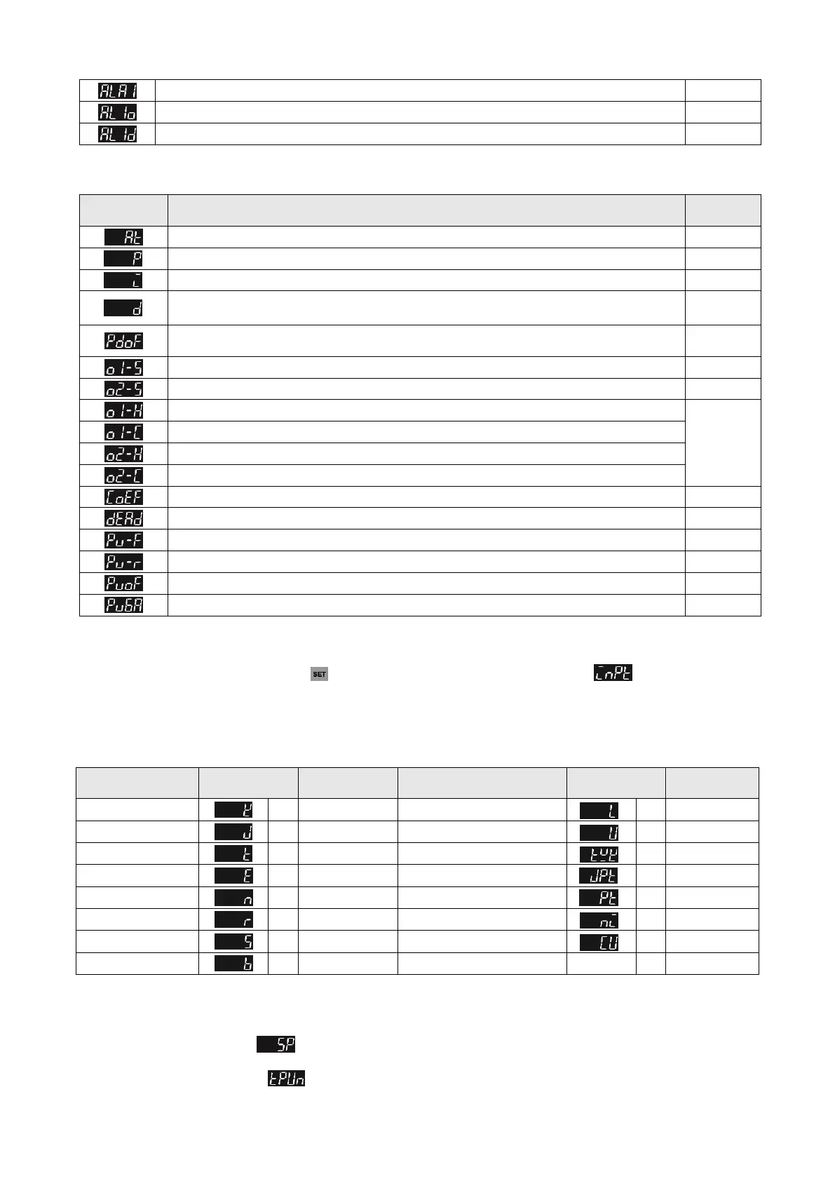
Parameter Settings for Regulation Mode:
AT: Auto-tuning Switch (display when setting Ctrl = PID/RUN)
P: Proportional Setting (display when setting Ctrl = PID and TUNE = AT)
I: Integral Time Setting (display when Crtl = PID; this parameter is set automatically when TUNE = AT.)
D: Deviation Time Setting
(display when Crtl = PID; this parameter is set automatically when TUNE = AT.)
PD OFFSET: PD offset when Integral = 0 to eliminate a consistent deviation.(display when Crtl = PID;
this parameter is set automatically when TUNE = AT.)
OUT1 HYSTERESIS: Adjust Output 1 hysteresis (when in ON/OFF control)
OUT2 HYSTERESIS: Adjust Output 2 hysteresis (when in ON/OFF control)
OUT1 HEAT: Heating control cycle for Output 1 (when Ctrl = PID/MANUAL)
Output
selection:
C; V: 5 sec.
R output
20 seconds
OUT1 COOL: Cooling control cycle for Output 1 (when Ctrl = PID/MANUAL)
OUT2 HEAT: Heating control cycle for Output 2 (when Ctrl = PID/MANUAL)
OUT2 COOL: Cooling control cycle for Output 2 (when Ctrl = PID/MANUAL)
COEF: Ratio of Output 1 against Output 2 (when Ctrl = PID and when in dual output control)
DEAD: Set up deadband (when Ctrl is not set to MANUAL and when in dual output)
PV FILTER: Set up input filter factor of PV
PV RANGE: Set up input filter range of PV
PV OFFSET: Adjust input compensation of PV
PV GAIN: Adjust input gain of PV
Initial Start-up Setting
When setting up DTI for the first time, press key for more than 3 seconds till the screen display and select according to
your temperature sensor type. Please be aware that incorrect selection of a model would cause PV temperature display error. (Refer to
the chart below)
When setting up the temperature sensor type by using RS-485, write your value (range 0~14) into register 1004H.
Temperature Sensor Type & Temperature Range Chart
Input Temperature
Sensor Type
Input Temperature Sensor Type
Platinum Resistance (JPt100)
Platinum Resistance (Pt100)
Display Unit Setting
Use following parameter to change the PV and SV display unit, select decimal point and switch between ℃/℉.
In Operation Mode parameter : SP = 1 displays decimal place (ex: 25.5 degree); SP = 0 displays integral number (ex: 25
degree).
In Initial Setting Mode parameter : Select temperature display unit ℃/℉. (℉=℃* 9 / 5 + 32)

 Loading...


