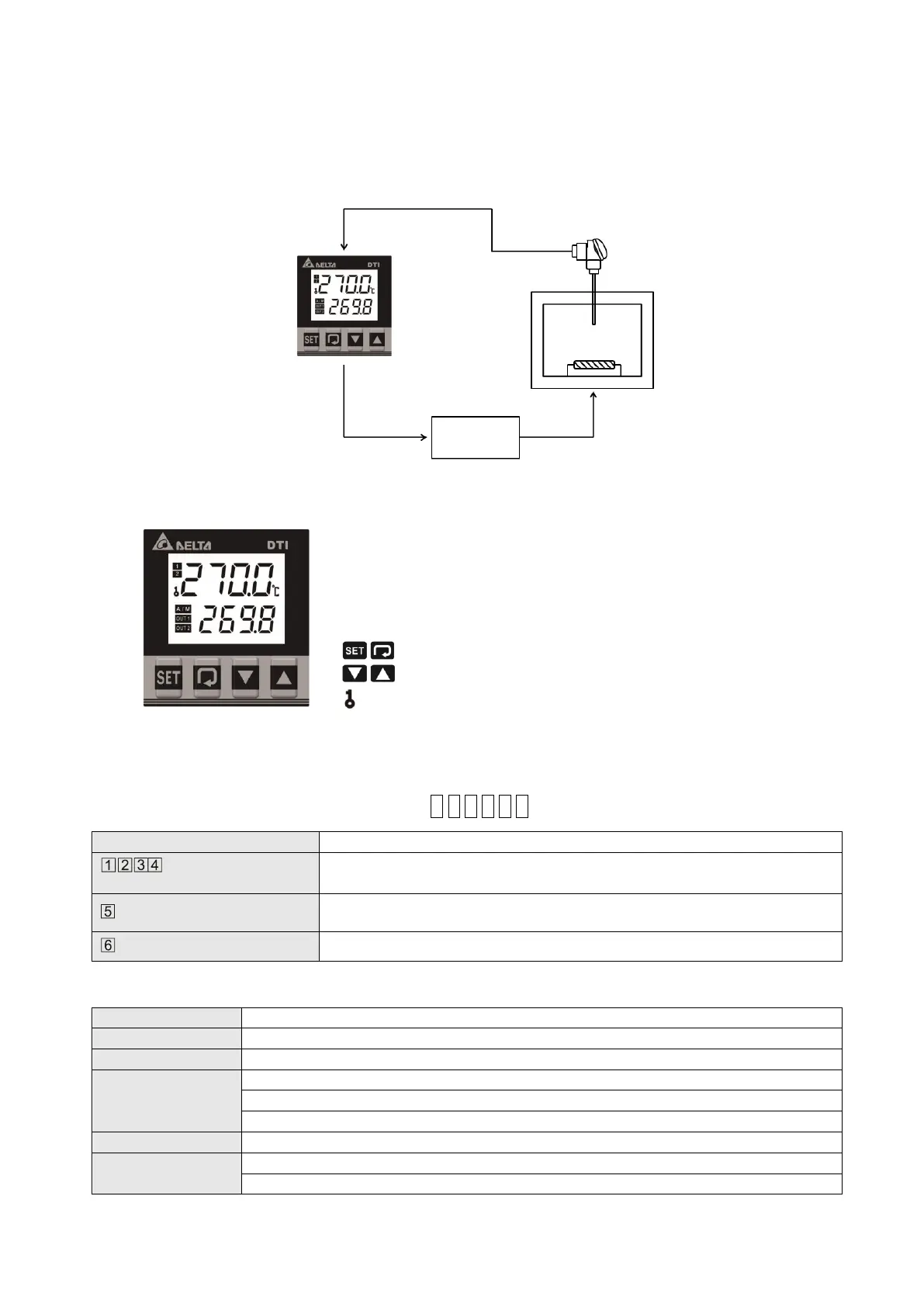
Basic System Structure
DTI obtains the temperature of the controlled environment from the sensor and sending the measured data to the electronic processor.
After computing and under a fixed control cycle, it proportionally sends the heating signal via different output interfaces such as relays,
voltage pulse or DC currents. By providing power to the heater and raise temperature, DTI will then control the temperature variation
within a specific range.
Display, LED & Pushbuttons
PV: Present value
SV: Set value
℃, ℉: Celsius or Fahrenheit LED
1: ALM1 alarm output LED
A/M: Auto-Tuning and manual mode LED
OUT1, OUT2: Output LED
: "Select" and "Set up" keys
: "Set value tuning" keys
: Button locking indicator
Ordering Information
DTI 1 2 3 4 5 6
DTI: Delta DTI Series Temperature Controller
4848:4848 1/16 DIN W48 × H48mm
9696:9696 1/4 DIN W96 × H96mm
R: Relay output, 250 VAC, 3A
V: Voltage pulse output 14VDC +/-15%
AC 100 ~ 240V +/-10%, 50/60 Hz
LCD display.Process value (PV): Red color, Set point (SV): Green color
Thermocouple: K, J, T, E, N, R, S, B, L, U, TXK
3-wire Platinum RTD: Pt100, JPt100
Relay output: Max. load 250VAC, 3A resistive load
Voltage pulse output: DC 14V, Max. output current 40 mA
Control Output
(Realy)
(DC Pulse)

 Loading...


