EasyManua.ls Logo

Delta DTI Series User Manual

Delta DTI Series
10 pages
To Next Page IconTo Next Page
To Previous Page IconTo Previous Page
Page #6 background imageLoading...
Page #6 background image
6
Output of when in PID control mode (Ctrl = PID):
When the controller is in PID control and dual loop output mode,
parameter sets the P value of the 2nd set of PID. The 1st set of PID is generated when TUNE = AT, but user can also
manually set the PID value. The P value of the 2nd set of PID = the P value of 1st set of PID x . The I and D value of the
2nd set of PID remains the same as the 1st set of PID.
Control Mode Setting
There are 3 control modes, which are ON-OFF, PID, and MANUAL.
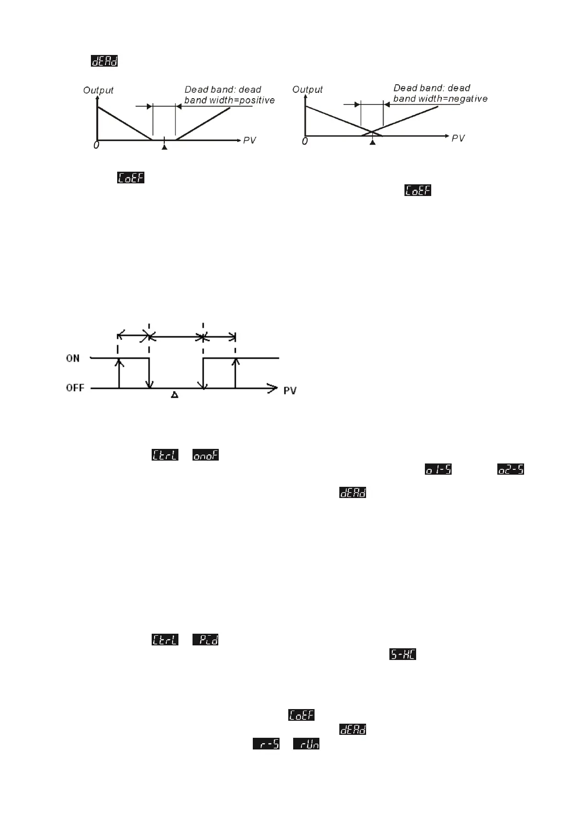
ON-OFF Mode: For heating output, the output is off when input is greater than the setting value; output is on when input is smaller
than (setting value - adjustment sensitivity setting value). For cooling output, the output is on when the input is greater than (setting
value + adjustment sensitivity setting value); output is off when input is smaller than the setting value. If one of 2 outputs is set for
heating and the other for cooling, a non-action zone can be set as shown in the diagram below.
Set parameter to in Initial Setting Mode.
Set adjustment sensitivity: Via parameter in Regulation Mode, set adjustment sensitivity (output 1),
(output 2).
Setting of Dead Band for both outputs: Set Dead Band via parameter in Regulation Mode.
PID Mode: When setting for heating or cooling, the program performs PID operation via input temperature and setting temperature,
with the operation result output for control of the temperature. A PID parameter and control period must be set for this function;
these parameters can also be generated automatically via auto-tuning (AT).
a. Set PID parameters and the control period: PID parameters can be adjusted manually according to system characteristics or
created automatically by AT. Proportional error compensation is used when I parameter is set to 0 for adjusting reduced
deviation from time to reach the temperature.The Control Period is the period of PID operation, if the control period is 10
seconds, it means a PID operation is carried out every 10 seconds. The result is then output to control the temperature.If the
system heats up quickly, the control period shall not be set too long. For relay output, lifespan of the relay shall be considered.
A short control period will shorten the lifespan of relay.
b. Coef and DeadBand are added in the PID parameter for double output (one for heating and one for cooling). Coef refers to
the ratio between the first and second portions of output (P parameter of second group = Coef*P, Coef = 0.01~99.99).
DeadBand is the overlapping temperature of the P output for the first and second group.
Set parameter to in Initial Setting Mode.
To set for heating or cooling control: Select desired output control via parameter in Initial Setting Mode. If only
single output control is performed, items to be selected are H1 and C1 (H for heating, C for cooling, and 1 for output 1). If
dual output control is performed, the items to be selected are as follows: H1H2, C1H2,... C1C2 (H for heating, C for cooling,
1 for output 1, and 2 for output 2).
Set control period: In Regulation Mode parameter, PV is displayed as "o'x' - 'y'". 'x' is 1 (output 1) or 2 (output 2). 'y' is H
(heating) or C (cooling).
Set double output Coef: Set Coef value via parameter in Regulation Mode.
Setting of Dead Band for both outputs: Set Dead Band via parameter in Regulation Mode.
Set control to running mode: Set parameter to in Operation Mode.
Heatin
g
Coolin
g
Set Point
Set Point
Heating
Cooling
Dead Band
Adjust heating
hysteresis
Adjust cooling
Heating
Cooling
Set Value
(Output ON-OFF control for both actions)
Question and Answer IconNeed help?

Do you have a question about the Delta DTI Series and is the answer not in the manual?

Delta DTI Series Specifications

General IconGeneral
Control AlgorithmPID, Auto-tuning
SeriesDTI
Control ModePID, On-Off
InputThermocouple, RTD
OutputRelay
DisplayLED
Power Supply24V DC, 100-240V AC
CommunicationRS-485
Dimensions96x96mm

Summary

Precaution

General Safety Warnings

General safety warning for the controller and connected peripherals to prevent harm.

Electric Shock Hazard

Warning against touching AC terminals while power is supplied to prevent electric shock.

Open-Type Controller Application

Evaluate dangerous applications where serious injury or property damage may occur.

External Power Control Requirement

The controller requires an external switch or circuit-breaker for safety and operation.

Wiring and Installation Guidelines

Instructions on using solder-less terminals, preventing dust, avoiding interference, and proper wiring.

Product Features

High Resolution LCD Display

Features a high contrast LCD panel for easy monitoring and understanding.

High-Speed Sampling

100ms sampling time for fast external temperature measurement and response.

Compact Size

Shortened length of 60mm reduces installation space.

CE Certification

Conforms with CE international safety certification standards.

Basic System Structure

System Operation Overview

Explains how the controller measures temperature, processes data, and controls heating via outputs.

Display, LED & Pushbuttons

Interface Elements

Describes the PV/SV display, LEDs (Celsius/Fahrenheit, Alarm, Mode), and pushbutton functions.

Ordering Information

Model Selection Guide

Details series, panel size, output options, and communication options for ordering.

Specifications

Electrical and Input Specifications

Covers input voltage, power consumption, display method, sensor types, control modes, and output types.

Environmental and Physical Specs

Details alarm output type, display accuracy, sampling rate, vibration, shock, ambient temp, altitude, and humidity.

Operation Modes and Settings

Operation Modes Overview

Explains the three modes: Operation, Regulation, and Initial Setting, and how to switch between them.

Parameter Settings for Operation Mode

Lists parameters adjustable in Operation Mode, like RUN/STOP, decimal point, and alarm settings.

Parameter Settings for Initial Setting Mode

Lists parameters for initial setup, including input type, temperature unit, and limits.

Alarm Output Configuration

Alarm Settings and Modes

Details the 9 alarm modes, including deviation, absolute value, and hysteresis alarms.

Alarm Parameter Configuration

Explains how to set alarm delay, reverse, standby, and hold parameters.

Display Unit Setting

How to change the PV and SV display unit to Celsius or Fahrenheit and set decimal points.

Input Value Adjustment

Set Value and Input Limits

Setting the Set Value (SV) and configuring upper/lower input limits.

Digital Filter and Linear Compensation

Adjusting filter factors and linear compensation for signal stability and accuracy.

Firmware and Output Type Check

How to check firmware version, output type, and input type during startup.

Heating/Cooling/Alarm/Dual-Loop Control

Selecting and configuring control modes for heating, cooling, or alarm outputs.

Control Mode Settings

ON-OFF Control Mode

Describes the ON-OFF control logic for heating/cooling with adjustment sensitivity and dead band.

PID Control Mode

Explains PID operation, parameter setting, auto-tuning, and dual output control with Coef and DeadBand.

Advanced Settings and Functions

Auto-Tuning (AT) Function

How to perform auto-tuning to automatically generate PID parameters for optimal control.

Output Range Limits

Setting maximum and minimum limits for control output percentages.

Temperature Range Limits

Configuring upper and lower limits for the input temperature range.

Factory Settings Restore

Procedure to restore the controller to its factory default settings.

Key Lock Functionality

How to lock/unlock the keypad and change the password.

Alarm Output Details

Alarm Function Disabled

Setting for disabling alarm functions.

Deviation Alarms

Types 1-3 for deviation alarms based on PV relative to SV.

Absolute Value Alarms

Types 4-6 for alarms based on absolute PV values against limits.

Hysteresis Alarms

Types 7-8 for hysteresis alarms with ON/OFF switching points.

Disconnection Alarm

Type 9 for detecting sensor disconnection or incorrect connection.

Alarm Mode and Parameter Settings

How to set alarm mode, deviation limits, delay, reverse, standby, and hold.

Error Codes and Installation

Error Code Interpretation

Explains panel error codes like 'no', 'cont', 'SEn', 'Err' for sensor issues.

Panel Cutout Dimensions

Provides panel cutout dimensions for 4848 and 9696 series controllers.

Mounting and Bracket Installation

Step-by-step guide for installing the controller using mounting brackets for 4848 and 9696 series.

Wiring and Service

Wiring Diagrams and Precautions

Illustrates wiring diagrams for 4848 and 9696 series and provides wiring precautions.

Product Service Information

Information on where to find more temperature controller details and technical support.

Related product manuals