Set Value and Upper/Lower Limit of the Input Value
SV setting serves as reference for control.
Set the Upper Limit of Input Value: In Initial Setting Mode parameter , the upper limit input value must be set within the range
shown in the chart "Temperature Sensor Type & Temperature Range".
Set the Lower Limit of Input Value: In Initial Setting Mode parameter , the upper limit input value must be set within the range
shown in the chart "Temperature Sensor Type & Temperature Range".
Set the SV: This parameter can be set in Operation Mode. SV value must be set within the range for upper/lower limit of the input
value.
Digital Filter and Linear Compensation Setting
To avoid interferences on input signal that would cause instable display value, two parameters are provided below for users to set up with.
In Regulation Mode, parameters and can be used to adjust filter status.
Filter Factors (setting range = 0~50; factory setting = 2). Linear Compensation Gain Calculation equation: PV = (Last
displayed PV * n + Measured Value) / (n+1).
When the parameter value is small, the PV display is close to the Measured Value. When the parameter value is large, the PV
response is slow.
Filter Range (setting range = 0.10~10.00℃).If factory setting = 1, it means the controller will begin Digital Filter Calcaulation
when the Measured Value lies within the range of "Last displayed PV + / - 1.00℃". Therefore, it is recommended to set a larger value
when noise interference is serious enough to cause large temperature oscillations.
When PV display value is different from user's expectation, Linear Compensation can be adjusted via parameters and
in Regulation Mode.
Linear Compensation Value (setting range = -99.9 ~ 99.9). Linear Compensation Gain Calculation equation: PV = Measured
Value + Compensation Value.
For example: Measure Value = 25.0; Compensation = 1.2. After applying to the Compensation equation PV = 26.2.
Linear Compensation Gain (setting range = -0.999~0.999). Linear Compensation Gain Calculation equation: PV = Measured
Value * (1 + Gain/1.000) + Compensation.
For example: Measured Value = 25.0; Gain = 0.100. After applying to the Gain calculation equation PV = 25.0 * (1 + 0.100 / 1.000) =
27.5.
If temperature deviation is the same in every temperature, setting linear compensation value solves the deviation issue. If temperature
deviation varies upon different temperatures, calculate the linear deviation error and adjust the temperature by setting Gain and
Compensation value.
Check Firmware Version and Output Type
When the temperature controller is ON, the PV and SV display will show firmware version, output type, and input type during the first 3
seconds.
PV indicates the firmware version. Ex: V110 indicates firmware version V1.10.
SV (first digit) indicates the output type of OUT1.
N: No function, V: Voltage pulse output, R: Relay output.
SV (second digit) indicates the output type of OUT2. No display: No OUT2 (default), R: Relay output
The 3rd and 4th SV digit are input types.
K, J, T, E, N, R, S, B, L, U, TX (TXK), JP (JPT100), PT (Pt100), CU (CU50), NI (NI120)
Selection for Heating/Cooling/Alarm/Dual-Loop Output Control
DTI series features 1 set of Output Control (OUT1) and 1 set of Alarm Output (ALARM1), both of which are built-in.
Using 1 set of Output Control:
In Initial Setting Mode, set parameter to Heating (H1) or Cooling (C1) mode.
Using 2nd set of Output Control:
When the 1st set of alarm and the 2nd set of output control are used for dual output control, set parameter in Initial
Setting Mode to controls such as heating (H1H2), cooling (C1C2), heating/cooling (H1C2), or cooling/heating (C1H2).
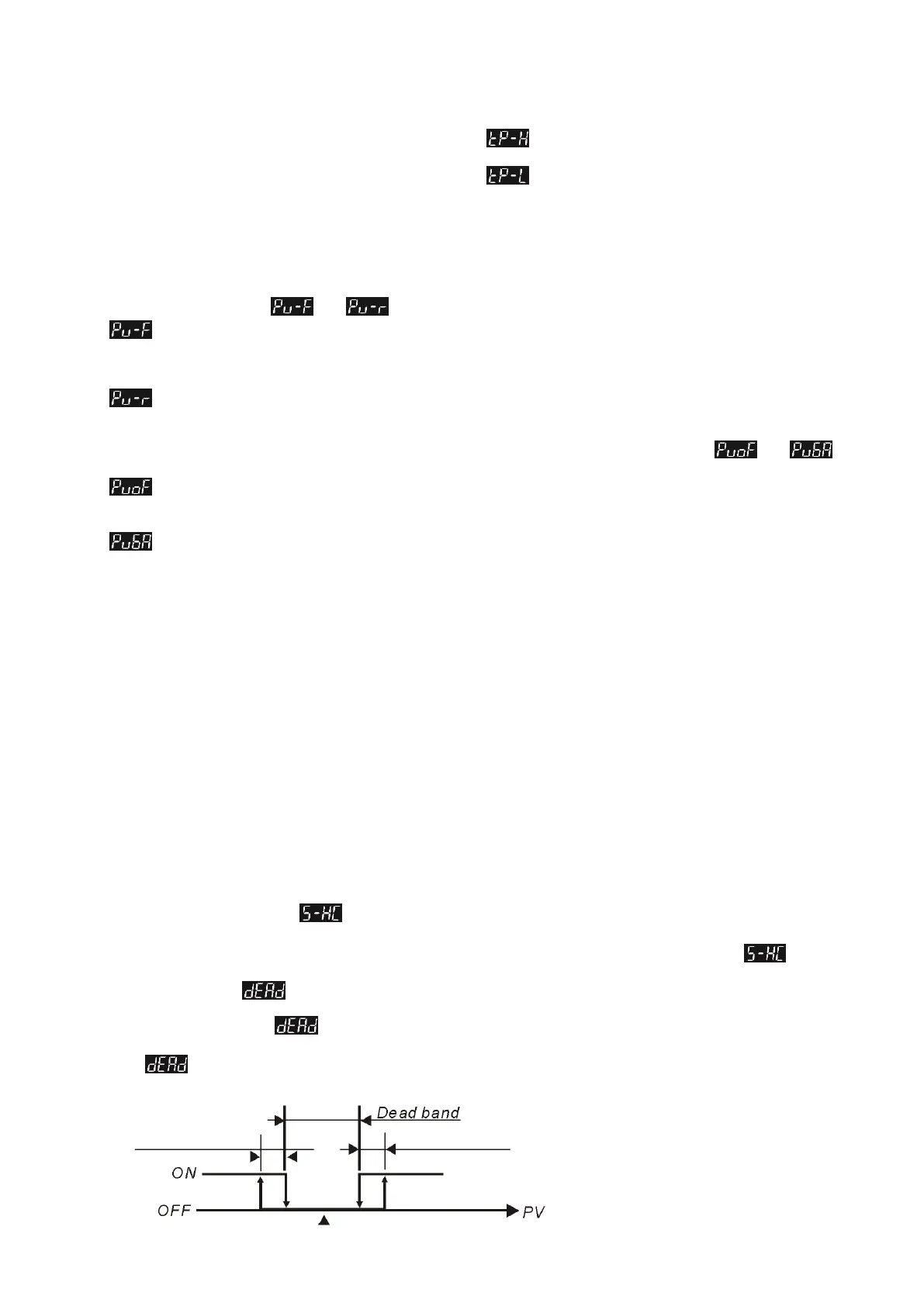
The Dead Band parameter is automatically enabled when the temperature controller is in dual output control. As shown in the
diagram below, the purpose for setting the Dead Band function is to reduce waste of energy from frequent acts of heating/cooling. Ex: For
example, if SV = 100 degree and = 2.0, there will be no output when the temperature is between 99~101°C.
Output of when in ON-OFF control mode (Ctrl = ON-OFF control):

 Loading...


