- 1 -
2020/12/02
Series Temperature Controller
Instruction Sheet
Thank you very much for purchasing DELTA B Series. Please read this instruction sheet before using your B series to ensure proper
operation and please keep this instruction sheet handy for quick reference.
Precaution
DANGER! Caution! Electric Shock!
1.
Do not touch the AC terminals while the power is supplied to the controller to prevent an electric shock.
2.
Make sure power is disconnected while checking the unit inside.
3.
The symbol indicates that this Delta B Series Temperature Controller is protected throughout by DOUBLE INSULATION or
REINFORCED INSULATION (equivalent to Class II of IEC 536).
WARNING!
This controller is an open-type temperature controller. Make sure to evaluate any dangerous application in which a serious human
injury or serious property damage may occur.
1.
Always use recommended solder-less terminals: Fork terminal with isolation (M3 screw, width is 7.0mm (6.0mm for DTB 4824), hole
diameter 3.2mm). Screw size: M3 x 6.5 (With 6.8 x 6.8 square washer). Screw size for DTB4824: M3 x 4.5 (With 6.0 x 6.0 square washer).
Recommended tightening torque: 0.4 N.m (4kgf.cm). Applicable wire: Solid/twisted wire of 2 mm
2
, 12AWG to 24AWG. Please be sure to
tighten them properly.
2.
Do not allow dust or foreign objects to fall inside the controller to prevent it from malfunctioning.
3.
Never modify or disassemble the controller.
4.
Do not connect anything to the “No used” terminals.
5.
Make sure all wires are connected to the correct polarity of terminals.
6.
Do not install and/or use the controller in places subject to:
Dust or corrosive gases and liquid
High humidity and high radiation
Vibration and shock
High voltage and high frequency
7.
Must turn power off when wiring and changing a temperature sensor.
8.
Be sure to use compensating wires that match the thermocouple types when extending or connecting the thermocouple wires.
9.
Please use wires with resistance when extending or connecting a platinum resistance thermometer (RTD).
10.
Please keep the wire as short as possible when wiring a platinum resistance thermometer (RTD) to the controller and please route power
wires as far as possible from load wires to prevent interference and induced noise.
11.
This controller is an open-type unit and must be placed in an enclosure away from high temperature, humidity, dripping water, corrosive
materials, airborne dust and electric shock or vibration.
12.
Please make sure power cables and signals from instruments are all installed properly before energizing the controller, otherwise serious
damage may occur.
13.
Please do not touch the terminals in the controller or try to repair the controller when power is applied to prevent an electric shock.
14.
Wait at least one minute after power is disconnected to allow capacitors to discharge, and please do not touch any internal circuit within
this period.
15.
Do not use acid or alkaline liquids for cleaning. Please use a soft, dry cloth to clean the controller.
16.
This instrument is not furnished with a power switch or fuse. Therefore, if a fuse or power switch is required, install the protection close to
the instrument. Recommended fuse rating: Rated voltage 250 V, Rated current 1 A. Fuse type: Time-lag fuse
17.
This controller does not provide overcurrent protection. Use of this product requires that suitable overcurrent protection device(s) must be
added to ensure compliance with all relevant electrical standards and codes. (Rated 250 V, 15 Amps max). A suitable disconnecting
device should be provided near the controller in the end-use installation.
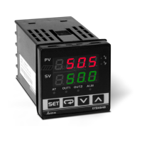
Display, LED & Pushbuttons