- 6 -
Dual Loop Output Control (Heating/Cooling Control)
Temperature control can be achieved either by heating or cooling. In DTB series, heating and cooling can be operated simultaneously (Dual
Loop output control) to perform temperature control. When Dual Loop output control are used, two control outputs must be connected to the
heating and cooling devices. Please refer to the following for the operation:
: This parameter is used to select heating or cooling action if operate either heating or cooling function in this controller. When
selecting , 1st output group is heating (reverse) control, and when selecting , 1st output group is cooling (forward) control. At this
moment, 2nd output group is regarded as an alarm output. If user select or , it indicates that user can operate Dual Loop output
control function in this controller. When selecting , 1st output group is heating (reverse) control and 2nd output group is cooling (forward)
control. When selecting , 1st output group is cooling (forward) control and 2nd output group is heating (reverse) control.
In DTB series, P (Proportional Band), I(Integral Time) and D(Derivative Time) parameters are automatically set by using the Auto-tuning (AT)
function.
: This parameter is for the control mode that must be Dual Loop output control with PID control method configured. The value of P, I and
D of 1st output group can be set immediately. The P value of 2nd output group is equal to (P value of 1st output group) x and the value
of I and D of 2nd output group are the same as the value of I and D of 1st output group.
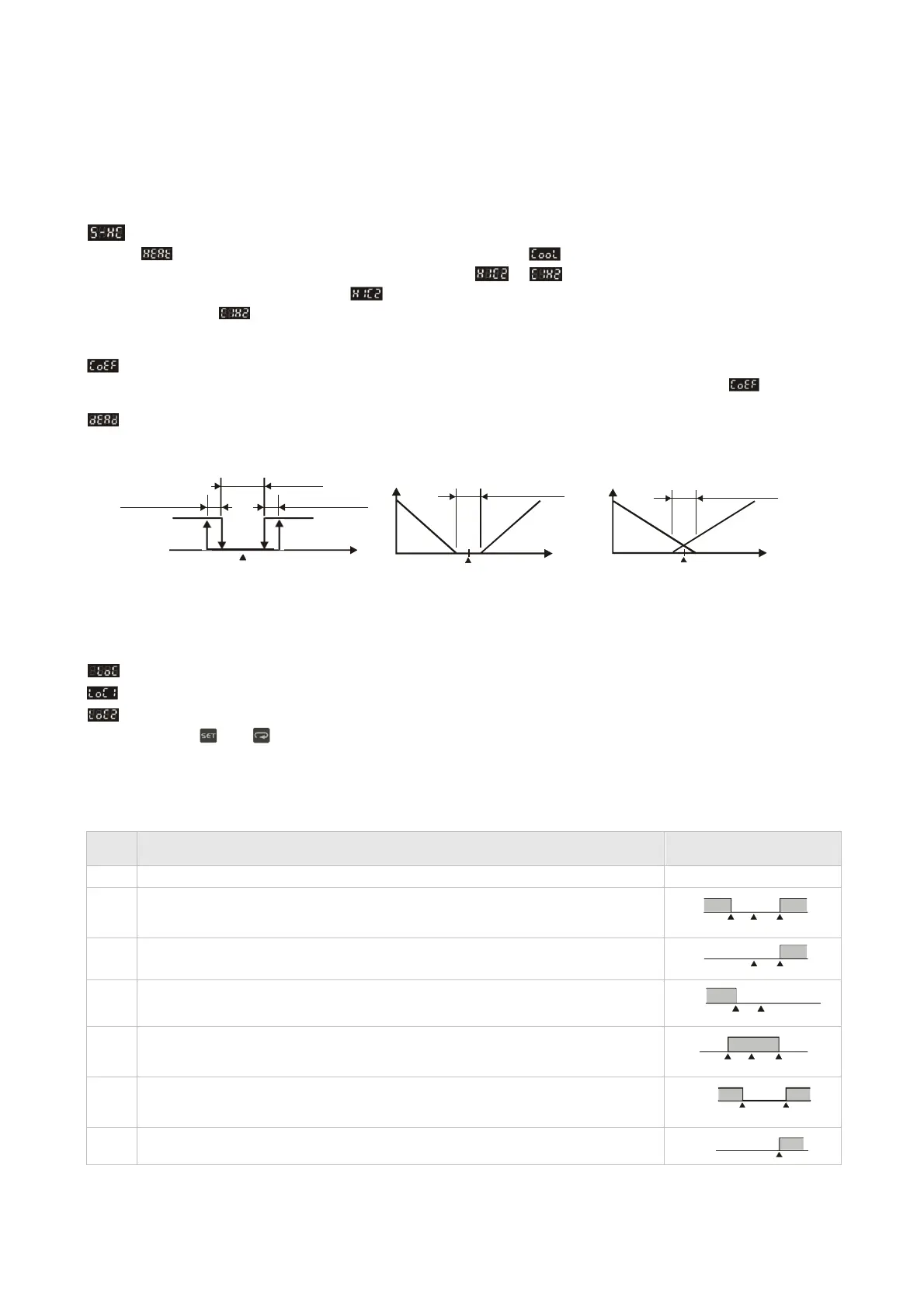
: Dead Band, shown as the following figure 1, 2 and 3. This parameter sets an area in which the heating and cooling control output is 0
centering around the set point in a Dual Loop output control mode.
Heating hysteresis
ON
Heating
Dead band
Cooling hysteresis
Cooling
Output
Dead band: dead
band width=positive
Output
Dead band: dead
band width=negative
OFF
PV
Set point
Figure 1. Output operation of ON/OFF control
Heating
0
Set point
Cooling
PV
Heating
Cooling
0
PV
Set point
during dual loop output control
Figure 2. PID control, Dead Band is positive
Figure 3. PID control, Dead Band is negative
:
Settings lock.
To avoid incorrect operation, two key lock functions are provided.
: Lock 1 can lock all settings. All parameters and temperature settings can be locked to disable changes.
: Lock 2 can lock settings except the SV (Set point) value. All parameters and temperature settings can be locked with the exception of
the SV value. Press and key simultaneously, the “Lock” status can be released.
Alarm Outputs
There are up to three groups of alarm outputs and each group allows eighteen alarm types in the initial setting mode. The alarm output is
activated whenever the process temperature value (PV) is getting higher or lower than the set point of alarm limit.
Set
value
Alarm Type
Alarm output operation
0
Alarm function disabled
Output is OFF
1
Deviation upper- and lower-limit:
This alarm output operates when PV value is higher than the setting value SV+(AL-H) or lower
than the setting value SV-(AL-L).
ON
OFF
SV-(AL-L)
SV
SV+(AL-H)
2
Deviation upper-limit:
This alarm output operates when PV value is higher than the setting value SV+(AL-H).
ON
OFF
SV
SV+(AL-H)
3
Deviation lower-limit:
This alarm output operates when PV value is lower than the setting value SV-(AL-L).
ON
OFF
SV-(AL-L)
SV
4
Reverse deviation upper- and lower-limit:
This alarm output operates when PV value is in the range of the setting value SV+(AL-H) and the
setting value SV-(AL-L).
ON
OFF
SV-(AL-L)
SV
SV+(AL-H)
5
Absolute value upper- and lower-limit:
This alarm output operates when PV value is higher than the setting value AL-H or lower than
the setting value AL-L.
ON
OFF
AL-L
AL-H
6
Absolute value upper-limit:
This alarm output operates when PV value is higher than the setting value AL-H.
ON
OFF
AL-H
 Loading...


