- 4 -
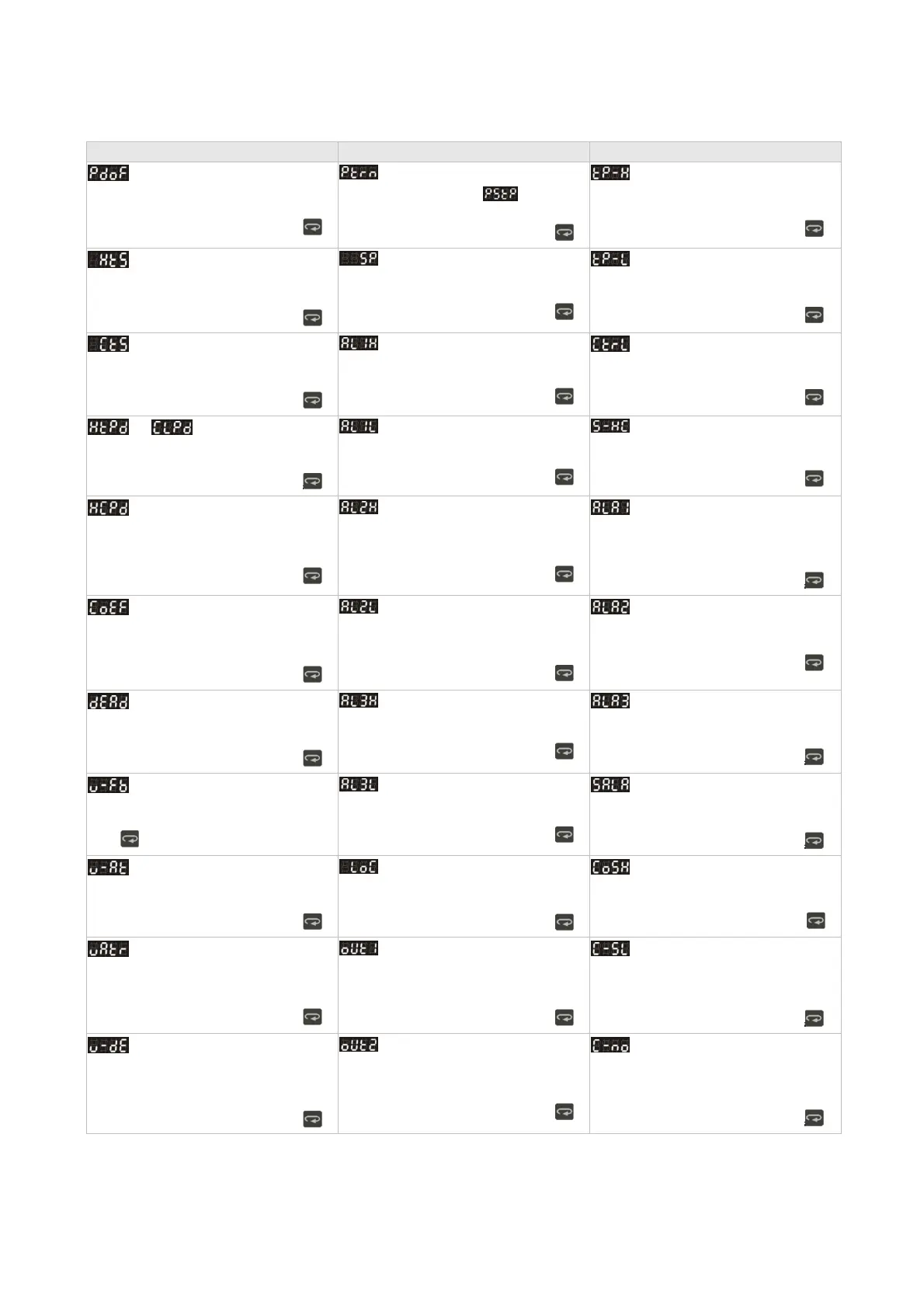
Regulation Mode
Operation Mode
Initial Setting Mode
PD control offset setting
(When PID control is ON and Ti=0, set the
value of PdoF.)
Press
Start pattern setting
(PID program control and Time
setting.
Press
Set upper-limit of temperature range
Press
Heating hysteresis setting
(Set in ON/OFF control mode)
Press
Decimal point position selection
(except for B, S, R type, all the other types
can be set)
Press
Set lower-limit of temperature range
Press
Cooling hysteresis setting
(Set in ON/OFF control mode)
Press
Upper-limit alarm 1
(This parameter is available only when ALA1
function is enabled.)
Press
Select control mode (See “Pattern
and Set Editing Selection” for detail)
Press
or Heating/Cooling control
cycle setting (Set in PID control mode)
Press
Lower-limit alarm 1 (This parameter
is available only when ALA1 function is
enabled.)
Press
Select heating/cooling control or dual
loop output control
Press
Control cycle setting of 2
nd
output
group
(Set in PID control and Dual Loop output
control mode)
Press
Upper-limit alarm 2 (This parameter is
available only when ALA2 function is
enabled.)
Press
Alarm 1 mode setting
Press
P value of 1
st
& 2
nd
output group
during dual loop output control
P value of 2
nd
output group=(P value of 1
st
output group x COEF
Press
Lower-limit alarm 2 (This parameter is
available only when ALA2 function is
enabled.)
Press
Alarm 2 mode setting
Press
Deadband
(Set in Dual Loop output control mode)
Press
Upper-limit alarm 3 (This parameter is
available only when ALA3 function is
enabled.)
Press
Alarm 3 mode setting
Press
Switch setting for feedback signal of
value (Displayed with valve control is ON)
Press
Lower-limit alarm 3 (This parameter is
available only when ALA3 function is
enabled.)
Press
Set system alarm
Press
Automatically regulate feedback
value
(Displayed when valve control is ON)
Press
Setting lock mode
Press
Enable/disable communication write
function
Press
Time setting for valve from full close
to full open (Displayed when valve control is
ON)
Press
Display and adjust output value of 1st
output group
(Display in PID control mode and manual RUN
mode)
Press
ASCII, RTU communication formats
selection
Press
Valve Deadband setting
(Displayed when valve control is ON)
Press
Display and adjust output value of 2
nd
output group
(Display in dual loop PID control mode and
manual RUN mode)
Press
Communication address setting
Press
 Loading...


