5
Set Value and Upper/Lower Limit of the Input Value
SV setting serves as reference for control.
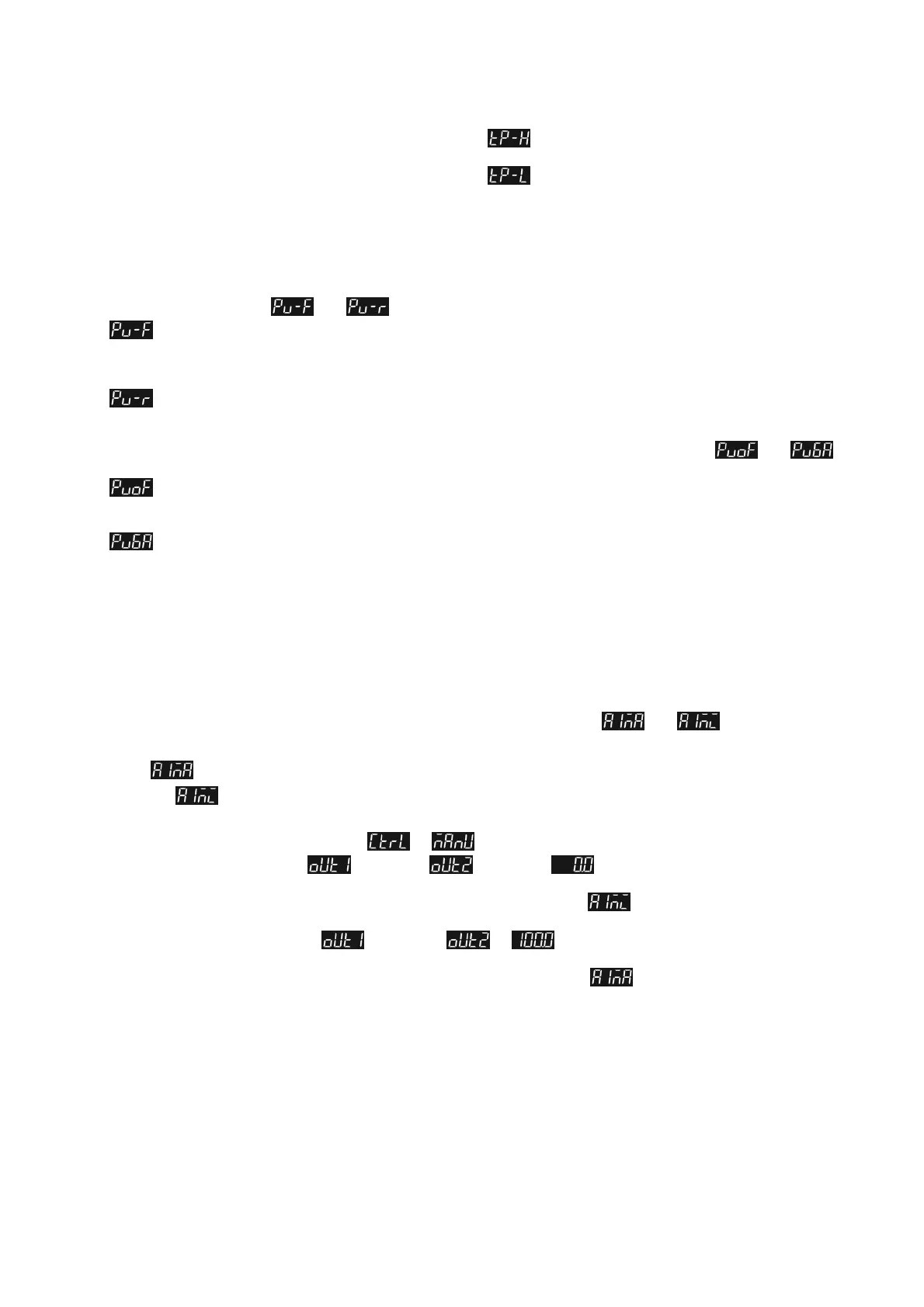
Set the Upper Limit of Input Value: In Initial Setting Mode parameter , the upper limit input value must be set within the range
shown in the chart "Temperature Sensor Type & Temperature Range".
Set the Lower Limit of Input Value: In Initial Setting Mode parameter
, the upper limit input value must be set within the range
shown in the chart "Temperature Sensor Type & Temperature Range".
Set the SV: This parameter can be set in Operation Mode.
SV value must be set within the range for upper/lower limit of the input
value.
Digital Filter and Linear Compensation Setting
To avoid interferences on input signal that would cause instable display value, two parameters are provided below for users to set up with.
In Regulation Mode, parameters
and can be used to adjust filter status.
Filter Factors (setting range = 0~50; factory setting = 2). Linear Compensation Gain Calculation equation: PV = (Last
displayed PV * n + Measured Value) / (n+1).
When the parameter value is small, the PV display is close to the Measured Value. When the parameter value is large, the PV
response is slow.
Filter Range (setting range = 0.10~10.00 ).If factory setting = 1, it means the controller will begin Digital Filter Calcaula℃ tion
when the Measured Value lies within the range of "Last displayed PV + / - 1.00 ". Therefore, it is recommended to set a larger value ℃
when noise interference is serious enough to cause large temperature oscillations.
When PV display value is different from user's expectation, Linear Compensation can be adjusted via parameters
and
in Regulation Mode.
Linear Compensation Value (setting range = -99.9 ~ 99.9). Linear Compensation Gain Calculation equation: PV = Measured
Value + Compensation Value.
For example: Measure Value = 25.0; Compensation = 1.2. After applying to the Compensation equation PV = 26.2.
Linear Compensation Gain (setting range = 0~0.999). Linear Compensation Gain Calculation equation: PV = Measured
Value * (1 + Gain/1.000) + Compensation.
For example: Measured Value = 25.0; Gain = 0.100. After applying to the Gain calculation equation PV = 25.0 * (1 + 0.100 / 1.000) =
27.5.
If temperature deviation is the same in every temperature, setting linear compensation value solves the deviation issue. If temperature
deviation varies upon different temperatures, calculate the linear deviation error and adjust the temperature by setting Gain and
Compensation value.
Analog Output Compensation
When the output mode is set to analog current output (4~20 mA), user's desired output value can be obtained by using compensation
function. For example, the analog output 1 can be adjusted for compensation in parameters
and in Regulation Mode.
The output value can be positive or negative (+/-) and can be changed by pressing the Up/Down key on the temperature controller. The
scale of each pressing is an increase or decrease of 1 uA. Ex: To change the current output range from 4~20 mA to 3.9~20.5 mA, set
parameter
to 500. (20.5-20=0.5mA; 0.5mA/1uA= 500)
Set parameter
to -100. (3.9-4=-0.1mA; -0.1mA/1uA=-100)
To control the output manually: Set parameter
to in Initial Setting Mode.
To set output to 0%: Set parameter
(output 1) or (output 2) to in Operation Mode.
To adjust the lower limit of analog output: Input a desired value and check the meter to adjust the analog input value to the desired
value (for example: 4~20 mA, adjusting analog value will be 4 mA). Set parameter
to your desired value in Regulation
Mode.
To set output to 100%: Set parameter
(Output 1) or to in Operation Mode.
To adjust the upper limit of analog output: Input a desired value and check the meter to adjust the analog input value to the desired
value (for example: 4~20 mA, adjusting analog value will be 20 mA). Set parameter to your desired value in Regulation
Mode.
Check Firmware Version and Output Type
When the temperature controller is ON, the PV and SV display will show firmware version, output type, and input type during the first 3
seconds.
PV indicates the firmware version. Ex: V110 indicates firmware version V1.10.
SV (first digit) indicates the output type of OUT1.
N: No function, V: Voltage pulse output, R: Relay output, C: Current output
SV (second digit) indicates the output type of OUT2. No display: No OUT2 (default), R: Relay output
The 3rd and 4th SV digit are input types.
K, J, T, E, N, R, S, B, L, U, TX (TXK), JP (JPT100), PT (Pt100), CU (CU50), NI (NI120)
 Loading...


