9
7
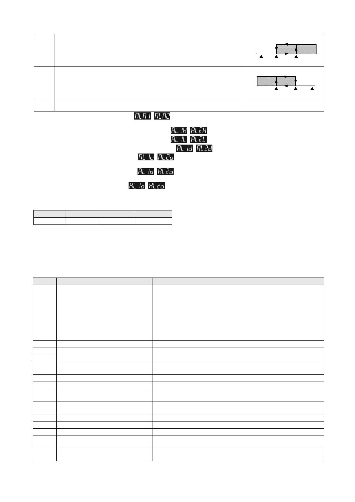
Hysteresis upper limit alarm output:
This alarm output operates when PV value is
higher than the setting value SV+(AL-H). This alarm output is OFF when PV value is
lower than the setting value SV+(AL-L).
ON
OFF
SV SV+(AL-L) SV+(AL-H)
8
Hysteresis lower limit alarm output:
This alarm output operates when PV value is
lower than the setting value SV-(AL-H). This alarm output is OFF when PV value is
higher than the setting value SV-(AL-L).
ON
OFF
SV-(AL-H) SV-(AL-L) SV
9
Disconnection Alarm: This alarm output operates if the sensor connection is incorrect
or has been disconnected.
To set Alarm Mode: Use the parameters , in Initial Setting Mode to select the alarm mode. There are 9 different
modes (as shown in the table above).
To set Deviation Upper Limit of Alarm:
Use the parameters , in Operation Mode to set the deviation upper limit.
To set Deviation Lower Limit of Alarm:
Use the parameters , in Operation Mode to set the deviation lower limit.
To set Alarm Delay Time (Unit: seconds): Use the parameters
, in Initial Setting Mode to set the alarm delay time.
To set Reverse Alarm: Use the parameters
, in Initial Setting Mode to set value of the corresponding position Y in
xxYx (when Y = 0: forward, Y = 1: reverse).
To set Standby Alarm: Use the parameters
, in Initial Setting Mode to set value of the corresponding position Y in
xxxY (when Y = 0: normal opeartion, Y = 1: standby).
To set Hold Alarm: Use the parameters
, in Initial Setting Mode to set value of the corresponding position Y in xYxx
(when Y = 0: normal operation, Y = 1: Hold).
Note: Refer to the table below for corresponding flags for Standby Alarm, Reverse Alarm, Hold Alarm, and Peak Alarm.
RS-485 Communication
1. Supported transmission speed: 2400, 4800, 9600, 19200, and 38400 bps; Communication formats not supported: 7, N, 1 or 8, E, 2
or 8, O, 2; Communication protocol: Modbus (ASCII or RTU); Function code: 03H to read contents of register (max. 8 words). 06H to
write 1 (one) word into register.
2. Address and Content of Data Register:
Address Content Definition
1000H Present value (PV)
Expressed by current temperature with 0.1 scale as the measuring unit,
updated once every 0.1 second.
The following reading value indicates occurrence of error:
8002H: Initial process (temperature value not yet obtained)
8003H: Temperature sensor is not connected.
8004H: Type of temperature sensor incorrect
8006H: Unable to obtain temperature value, ADC input error.
8007H: Unable to read/write memory
1001H Set point (SV) Expressed by current temperature with 0.1 scale as the measuring unit.
1002H Upper limit of temperature range The data content should not be higher than the temperature range.
1003H Lower limit of temperature range The data content should not be lower than the temperature range.
1004H Input temperature sensor type
Please refer to “Temperature Sensor Type and Temperature Range” table for
detail of the compared value.
1005H Control method 0: PID, 1: ON/OFF, 2: Manual control
1006H Selection for Heating/Cooling control Refer to Output Mode Selection
1007H 1st set of Heating/Cooling control cycle
1~600, unit is 0.1 second. When the output setting = relay, the minimum
control cycle is 5 second.
1008H 2nd set of Heating/Cooling control cycle
1~600, unit is 0.1 second. When the output setting = relay, the minimum
control cycle is 5 second.
1009H PB Proportional band 0.1 ~ 999.9
100AH Ti Integral time 0~9999
100BH Td Derivative time 0~9999
100DH
Proportional control offset error value,
when Ti = 0.
0 ~ 100%, unit is 0.1%.
100EH
The setting of COEF when Dual Loop
output controls are used.
0.01 ~ 99.99, unit is 0.01.
Bit3 Bit2 Bit1 Bit0
No function Hold Alarm Reverse Alarm Standby Alarm
 Loading...


