DVP04AD-S2
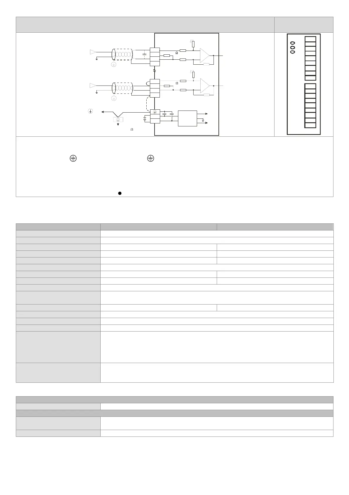
Arrangement of the
terminals
-10V~+10V
V1+
I1+
COM1
CH1
-20mA~+20mA
V4+
I4+
COM4
CH4
*5
*2
24V
0V
DC24V
+15V
-15V
AG
*4
FG
FG
*3
CH1
1M
AG
1M
250
CH4
1M
AG
1M
250
Shielded
cable*1
Voltage input
Shielded
cable*1
Current input
Connected to on
a power supply module
DC/DC
converter
System ground
Ground (Impedance: Less than 100 )
V1+
I1+
COM1
FG
V3+
.
.
I2+
COM2
FG
V2+
I3+
COM3
FG
I4+
COM4
FG
V4+
Note 1: Please isolate the analog input cable from other power cables.
Note 2: If current is connected, the connection between V+ and I+ (the connection between V4+ and I4+) needs to be a short circuit.
Note 3: If there is much noise, please connect the terminal FG to the ground terminal.
Note 4: Please connect
on a power supply module and on the analog input module to the system ground, and then ground the system
ground or connect the system ground to a distribution box.
Note 5: If ripple voltage results in interference with the wiring, please connect a 0.1~0.47 μF and 25 V capacitor.
※
Use cables with the same length (less than 200 m) and wire resistance of less than 100 ohm.
Warning: DO NOT wire to the empty terminal
.
Specifications
Functions
Analog/Digital (4A/D) module Voltage input Current input
Power supply voltage 24VDC (20.4VDC ~ 28.8VDC) (-15% ~ +20%)
Analog input channel 4 channel/each module
Analog input range ±10V ±20mA
Digital conversion range ±8,000 ±4,000
Resolution 14 bits (1
LSB
=1.25mV) 13 bits (1
LSB
=5μA)
Overall accuracy 0.5% of full scale of 25°C (77°F). 1% of full scale during 0 ~ 55°C (32 ~ 131°F)
Input impedance (DVP04AD-S) 200KΩ 250Ω
Input impedance (DVP04AD-S2) ≧1MΩ 250Ω
Response time 3ms × Number of channels
Isolation method
The analog circuit is isolated from the digital circuit by an optocoupler, but the analog channels
are not isolated from one other.
Absolute input range ±15V ±32mA
Digital data format 16-bit 2’s complement
Average function Yes (CR#2 ~ CR#5 can be set and setting range is K1 ~ K20)
Self diagnose function Upper and lower bound detection/channels
Communication mode (RS-485)
Supported, including ASCII/RTU mode. Default communication format: 9600, 7, E, 1, ASCII; refer
to CR#32 for details on the communication format.
Note1: RS-485 cannot be used when connected to CPU series PLCs.
Note2: Refer to Slim Type Special Module Communications in the appendix E of the DVP
programming manual for more details on RS-485 communication setups.
Connecting to a DVP series PLC
If DVP04AD-S/DVP04AD-S2 modules are connected to a PLC, the modules are numbered from
0 – 7. 0 is the closest and 7 is the furthest to the PLC. 8 modules is the max and they do not
occupy any digital I/O points of the PLC.
Others
Power specification
Max.
ated consumin
powe
24VDC
20.4VDC ~ 28.8VDC
-15% ~ +20%
, 2W, suppl
from external powe
.
Environment condition
Operation/storage
1. Operation: 0°C ~ 55°C (temperature), 5 ~ 95% (humidity), pollution degree 2
2. Stora
e: -25°C ~ 70°C
temperature
, 5 ~ 95%
humidit
Vibration/shock immunity Standard: IEC61131-2, IEC68-2-6 (TEST Fc)/IEC61131-2 & IEC68-2-27 (TEST Ea)
Installation and Wiring
Mounting Arrangements and Wiring Notes
 Loading...