DIN Rail Installation
The DVP-PLC can be secured to a cabinet by using the DIN rail that is
35mm high with a depth of 7.5mm. When mounting the PLC on the
DIN rail, be sure to use the end bracket to stop any side-to-side motion
of the PLC, thus to reduce the chance of the wires being pulled loose.
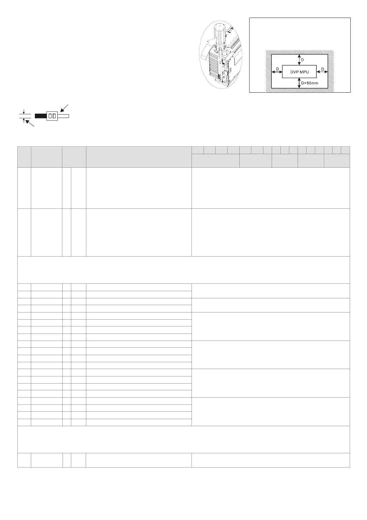
On the bottom of the PLC is a small retaining clip. To secure the PLC
to the DIN rail, place it onto the rail and gently push up on the clip. To
remove it, pull down on the retaining clip and gently pull the PLC away
from the DIN rail. Please see the figure on the right.
For heat dissipation. Make sure to
provide a minimum clearance of 50mm
between the unit and all sides of the
cabinet. (shown as below)
CR (Control Register)
CR#
RS-485
parameter
address
Latched Register name
b15 b14 b13 b12 b11 b10 b9 b8 b7 b6 b5 b4 b3 b2 b1 b0
Reserved CH4 CH3 CH2 CH1
#0 H’4000 ○ R Model type
For system use
Data length: 8 bits (b7 ~ b0)
Model code of DVP04AD-S: H’88
Model code of DVP04AD-S2: H’90
Users can read the model type by means of a program to
check if the expansion module exists.
#1 H’4001 ○ R/W Input mode setting
Input mode setting: The factory setting is H’0000.
Mode 0: Voltage input mode (-10V ~ +10V)
Mode 1: Voltage input mode (-6V ~ +10V)
Mode 2: Current input mode (-12mA ~ +20mA)
Mode 3: Current input mode (-20mA ~ +20mA)
Mode 7: Disabling a channel (Only applicable to
DVP04AD-S2)
CR#1: CR#1 is used to set 4 internal channels working mode of analog input module. Every channel has four modes to set that can be
set individually. For example: if set CH1 to mode 0 (b2 ~ b0 = 000), CH2 to mode 1 (b5 ~ b3 = 001), CH3: mode 2 (b8 ~ b6 = 010),
CH4: mode 3 (b11 ~ b9 = 011). Then CR#1 is set to H’0688 and the upper bit (b12 ~ b15) will reserved. The factory setting of CR#1 is
H’0000.
#2 H’4002 ○ R/W CH1 average times
Average times setting of channel CH1 ~ CH2.
Setting range is K1 ~ K20 and factory setting is K10.
#3 H’4003 ○ R/W CH2 average times
#4 H’4004 ○ R/W CH3 average times Average times setting of channel CH3 ~ CH4.
Setting range is K1 ~ K20 and factory setting is K10.
#5 H’4005 ○ R/W CH4 average times
#6 H’4006 ╳ R Average value of the CH1 input signal
Display average value of CH1 ~ CH4 input signal.
The default value in CR#2/CR#3/CR#4/CR#5 is 10, that is, the
average value of the CH1/CH2/CH3/CH4 input signal is
calculated every 10 times.
#7 H’4007 ╳ R Average value of the CH2 input signal
#8 H’4008 ╳ R Average value of the CH3 input signal
#9 H’4009 ╳ R Average value of the CH4 input signal
#12 H’400C ╳ R present value of CH1 input signal
Display present value of CH1 ~ CH4 input signal.
#13 H’400D ╳ R present value of CH2 input signal
#14 H’400E ╳ R present value of CH3 input signal
#15 H’400F ╳ R present value of CH4 input signal
#18 H’4012 ○ R/W To adjust OFFSET value of CH1
Offset setting of CH1 ~ CH4.
Factory setting is K0 and unit is LSB.
Voltage input: setting range is K-4,000 ~ K4,000.
Current input: setting range is K-4,000 ~ K4,000.
#19 H’4013 ○ R/W To adjust OFFSET value of CH2
#20 H’4014 ○ R/W To adjust OFFSET value of CH3
#21 H’ 4015 ○ R/W To adjust OFFSET value of CH4
#24 H’4018 ○ R/W To adjust GAIN value of CH1
GAIN setting of CH1 ~ CH4. Factory setting is K4,000 and unit
is LSB.
Voltage input: setting range is K-3,200 ~ K16,000.
Current input: setting range is K-3,200 ~ K10,400.
#25 H’4019 ○ R/W To adjust GAIN value of CH2
#26 H’401A ○ R/W To adjust GAIN value of CH3
#27 H’401B ○ R/W To adjust GAIN value of CH4
CR#18~CR#27: Please be noticed that GAIN value – OFFSET value=+800
LSB
~ +12,000
LSB
(voltage) or +800
LSB
~ +6,400
LSB
(current). If the value difference comes up small (within range), the output signal resolution is then slim and the variation is definitely
larger. On the contrast, if the value difference exceeds the range, the output signal resolution becomes larger and the variation is
definitely smaller.
#30 H’401E ╳ R Error status
It is the data register to save all error status.
Please refer to error code chart for detail.
Wiring
22-16AWG
< 1.5mm
1. Use 22-16AWG (1.5mm) single or multiple core wire on I/O wiring terminals. The specification of the
terminal is shown in the figure on the left hand side. The PLC terminal screws shall be tightened to
1.95kg-cm (1.7 in-lbs).
2. DO NOT place the I/O signal wires and power supply wire in the same wiring duct.
3. Use 60/75°C copper wires only.
 Loading...