12
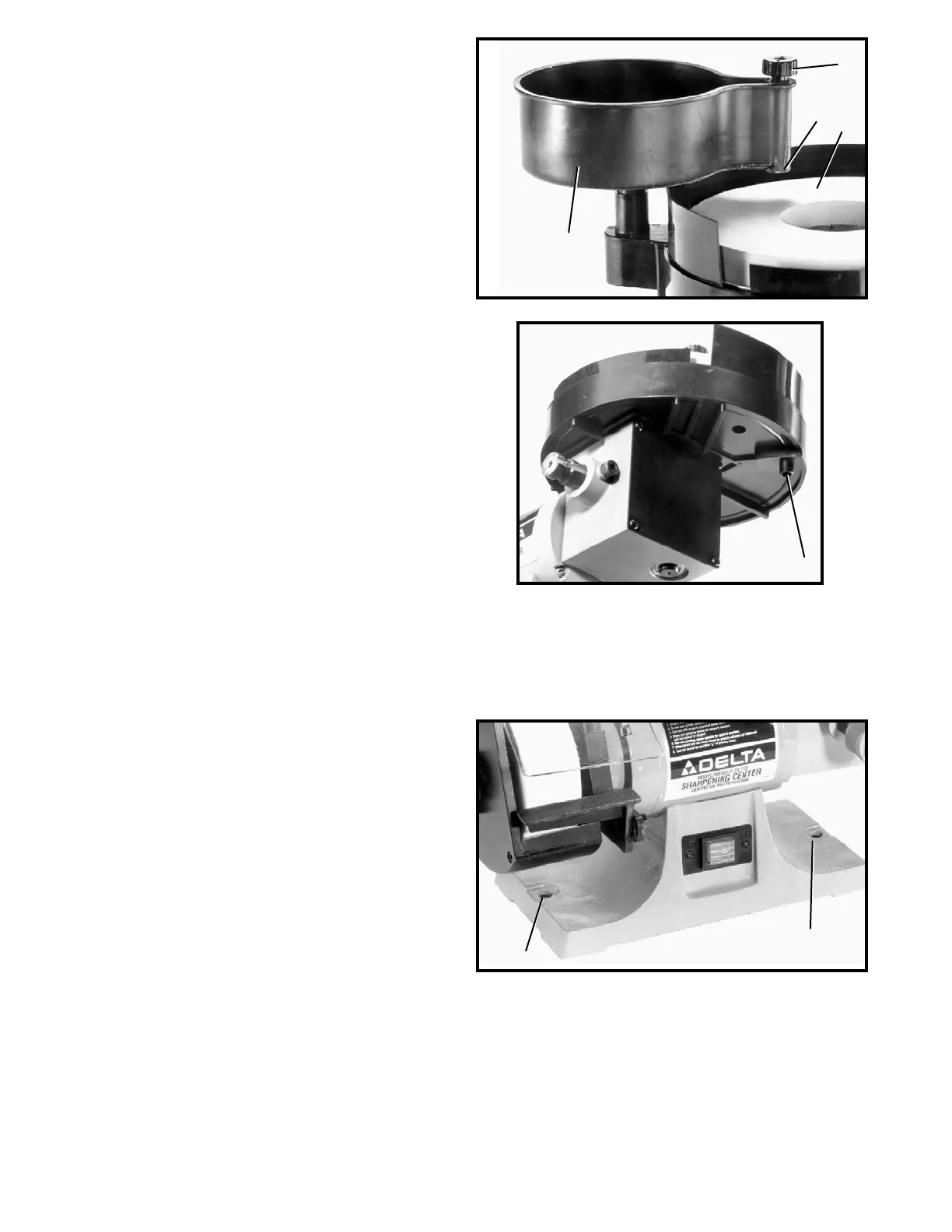
Fig. 19
Fig. 20
Fig. 21
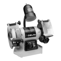
2. The water tank (B) Fig. 19, can be rotated to direct
the water from the spigot (D) onto the grinding wheel.
The ideal position of the spigot (D) would be to the
center (C) of the grinding wheel.
3. To control the flow of water from the spigot (D) Fig.
19, turn knob (E).
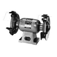
4. A drain (F) Fig. 20, is provided underneath the
grinding wheel housing to dispose of water. Place a
can or suitable container underneath the drain (F).
FASTENING SHARPENING CENTER
TO SUPPORTING SURFACE
If during operation there is any tendency for the machine
to tip over, slide or "walk" on the supporting surface, the
machine must be secured to the supporting surface. Two
holes, (A) Fig. 9, are provided for this purpose.
A
A
B
D
E
F
C
 Loading...