Chapter 7 Optional AccessoriesC2000 Plus
7-64
7-5 Zero Phase Reactors
Reactor Model* Recommended Wire Size Wiring Method Max. Wiring Q’ty
RF008X00A ≤ 8 AWG ≤ 8.37 mm
2
Diagram A
1C*3
or
4C*1
T60006L2040W453 ≤ 8 AWG ≤ 8.37 mm
2
Diagram B
RF004X00A ≤ 1 AWG ≤ 42.41 mm
2
Diagram A
1C*3
or
4C*1
T60006L2050W565 ≤ 1 AWG ≤ 42.41mm
2
Diagram B
RF002X00A ≤ 600 MCM ≤ 304 mm
2
Diagram A
1C*3
or
4C*1
T60006L2160V066 ≤ 600 MCM ≤ 304 mm
2
Diagram B
RF300X00A ≤ 350 MCM ≤ 185 mm
2
Diagram A
1C*12
or
4C*3
Table 7-71
NOTE:
1. Mark * means that motor cable is a 600V insulated power cable.
2. The table above only considers the motor cable size
3. For the max. wiring quantity, refer to Chapter 5 Main Circuit Terminal.
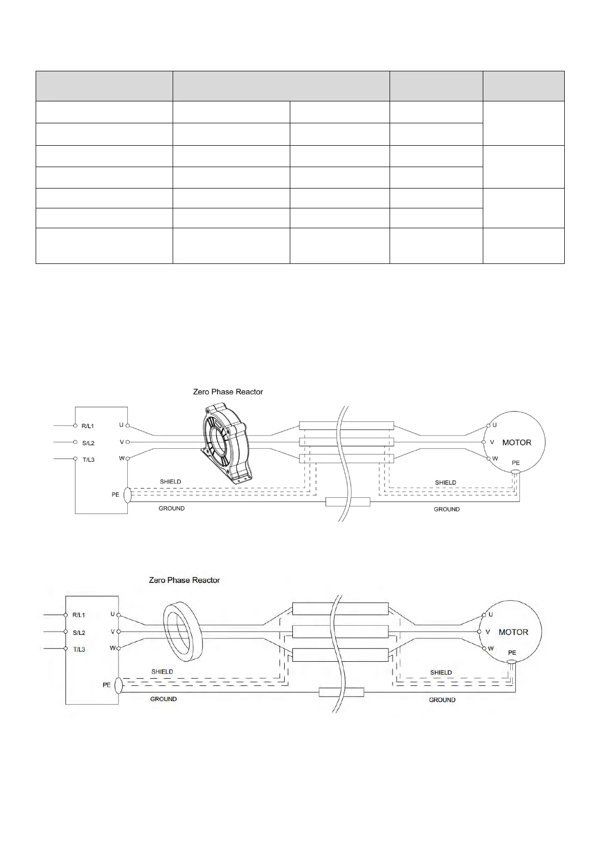
Diagram A
Put all wires through at least one core without winding.
Figure 7-39
Diagram B
Figure 7-40