Chapter 12 Descriptions of Parameter SettingsC2000 Plus
12.1-01-3
01-08
Motor 1 Minimum Output Voltage
Default:
Settings 230V models: 0.0–240.0 V 1.0
460V models: 0.0–480.0 V 2.0
575V models: 0.0–637.0 V 0.0
690V models: 0.0–720.0 V 0.0
01-41
Motor 2 Minimum Output Frequency
Default: 0.50
Settings 0.00–599.00 Hz
01-42
Motor 2 Minimum Output Voltage
Default:
Settings 230V models: 0.0–240.0 V 1.0
460V models: 0.0–480.0 V 2.0
575V models: 0.0–637.0 V 0.0
690V models: 0.0–720.0 V 0.0
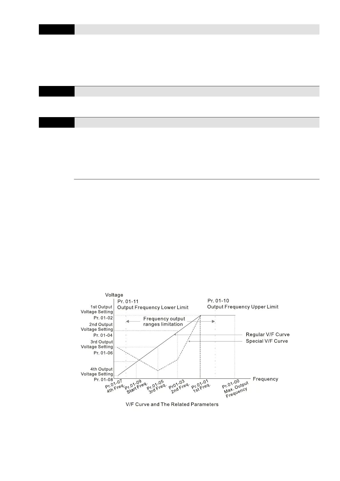
You usually set the V/F curve according to the motor’s allowable loading characteristics. Pay
special attention to the motor’s heat dissipation, dynamic balance, and bearing lubrication when
the loading characteristics exceed the loading limit of the motor.
There is no limit for the voltage setting, but a high voltage at a low frequency may cause motor
damage, overheating, and trigger the stall prevention or the over-current protection; therefore,
use low voltage at low frequency to prevent motor damage or drive error.
Pr.01-35 to Pr.01-42 is the V/F curve for motor 2. When setting the multi-function input terminals
[Pr.02-01–02-08 and Pr.02-26–Pr.02-31 (extension card)] to 14, the AC motor drive acts with the
second V/F curve.
The diagram below shows the V/F curve for motor 1. You can use the same V/F curve for motor
2.