Chapter 12 Descriptions of Parameter SettingsC2000 Plus
12.1-03-3
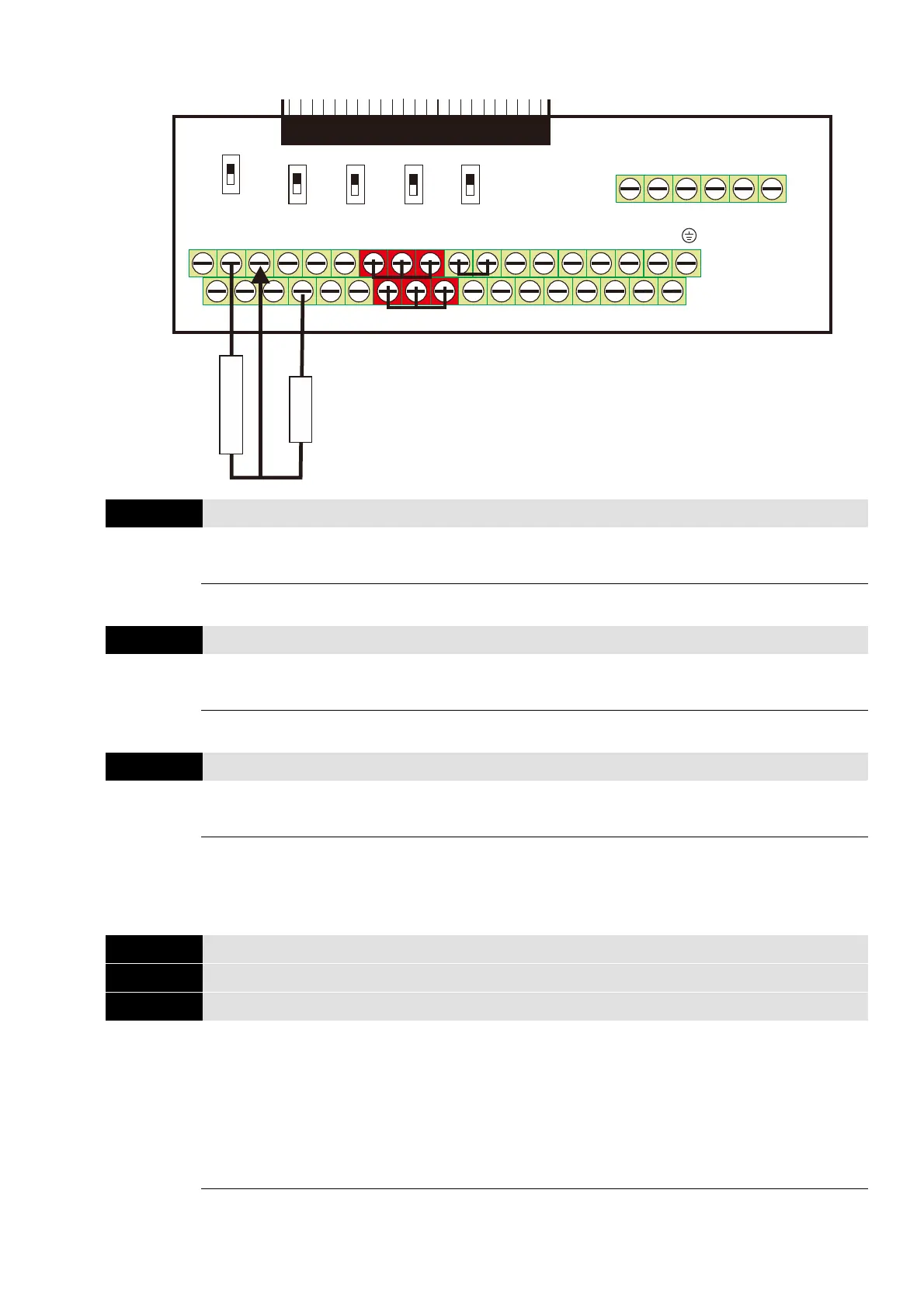
The wiring of KTY-84 as shown below
03-03
AVI Analog Input Bias
Default: 0.0
Settings -100.0–100.0%
Set the corresponding AVI voltage for the external analog input 0.
03-04
ACI Analog Input Bias
Default: 0.0
Settings -100.0–100.0%
Set the corresponding ACI current for the external analog input 0.
03-05
AUI Analog Input Bias
Default: 0.0
Settings -100.0–100.0%
Set the corresponding AUI voltage for the external analog input 0.
The corresponding external input voltage / current signal and the set frequency is 0–10 V (4–20
mA) corresponds to 0–maximum frequency.
03-07
AVI Positive / Negative Bias Mode
03-08
ACI Positive / Negative Bias Mode
03-09
AUI Positive / Negative Bias Mode
Default: 0
Settings 0: No bias
1: Lower than or equal to bias
2: Greater than or equal to bias
3: The absolute value of the bias voltage while serving as the center
4: Bias serves as the center
Using negative bias to set the frequency greatly reduces the noise interference. In a noisy
environment, do NOT use signals less than 1 V to set the drive’s operation frequency.
M I1+24V COM FWDMO1 MI5MI3ACI+10V AVIA FM1 MO2
MCM
MI7
M I4DCM RE V MI2 MI8MI6ACM-10V AUIAFM2
DFM
SG-SG+
R A2RC2 RB2 RB1RC1 RA1
0- 1 0V
-10-10V
0-10V 0-10V
0-10V
0-20mA
0-20mA
0-20mA Open
120
AFM1
AFM2
AVI
ACI 485
SGNDSTO1 STO 2
SCM1SCM2 DCM
+24V
Removable Terminal Block
KTY-84
Divider R1