Chapter 12 Descriptions of Parameter SettingsC2000 Plus
12.1-10-7
10-13
Encoder / Speed Observer Slip Range
Default: 50
Settings 0–50% (0: Disabled)
10-14
Detection Time of Encoder/ Speed Observer Slip
Default: 0.5
Settings 0.0–10.0 sec.
10-15
Encoder / Speed Observer Stall and Slip Error Action
Default: 2
Settings 0: Warn and continue operation
1: Fault and ramp to stop
2: Fault and coast to stop
Starts to accumulate time when the difference between rotational speed and motor frequency
exceeds the setting of speed observer slip range (Pr.10-13). If the accumulation time exceeds
the detection time of speed observer slip (Pr.10-14), then the large deviation of speed feedback
(SdDe, fault no. 70) fault occurs. Refer to Chapter 14 for fault treatment.
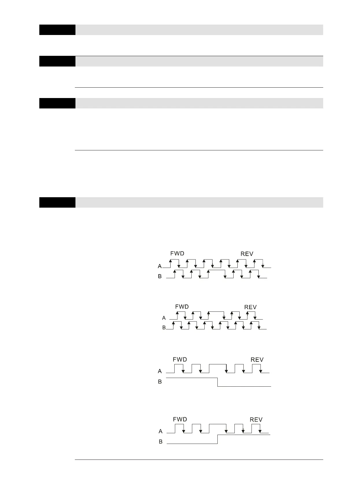
10-16
Pulse Input Type Setting
Default: 0
Settings 0: Disabled
1: A / B phase pulse input, run forward if A-phase leads B-phase by 90
degrees.
2: A / B phase pulse input, run forward if B-phase leads A-phase by 90
degrees.
3: A-phase is a pulse input and B-phase is a direction input
(L = reverse direction, H = forward direction).
4: A-phase is a pulse input and B-phase is a direction input
(L = forward direction, H = reverse direction).
5: MI8 single-phase pulse input (applied to 230V / 460V models)