Chapter 12 Descriptions of Parameter SettingsC2000 Plus
12.1-10-14
10-41
I/F Mode, Id Current Low Pass-Filter Time
Default: 0.2
Settings 0.0–6.0 sec.
Set the filter time for Pr.10-31. Smoothly increases the magnetic field to the current command
setting value under the I/F mode.
If you want to slowly increase the size of Id, increase the filter time to avoid a step phenomenon
occurs when starting current output. When decrease the filter time (minimum value is 0), the
current rises faster, then a step phenomenon occurs.
10-42
Initial Angle Detection Pulse Value
Default: 1.0
Settings 0.0–3.0
The angle detection is fixed to 3: Use the pulse injection method to start. The parameter
influences the value of the pulse during the angle detection. The larger the pulse, the higher the
accuracy of rotator’s position. A larger pulse might cause oc.
Increase the parameter when the running direction and the command are opposite during start-
up. If oc occurs at start-up, then decrease the parameter.
Refer to Section 12-2 Adjustment & Application for detailed motor adjustment procedure.
10-43
PG Card Version
Default: Read only
Settings 0.00–655.35
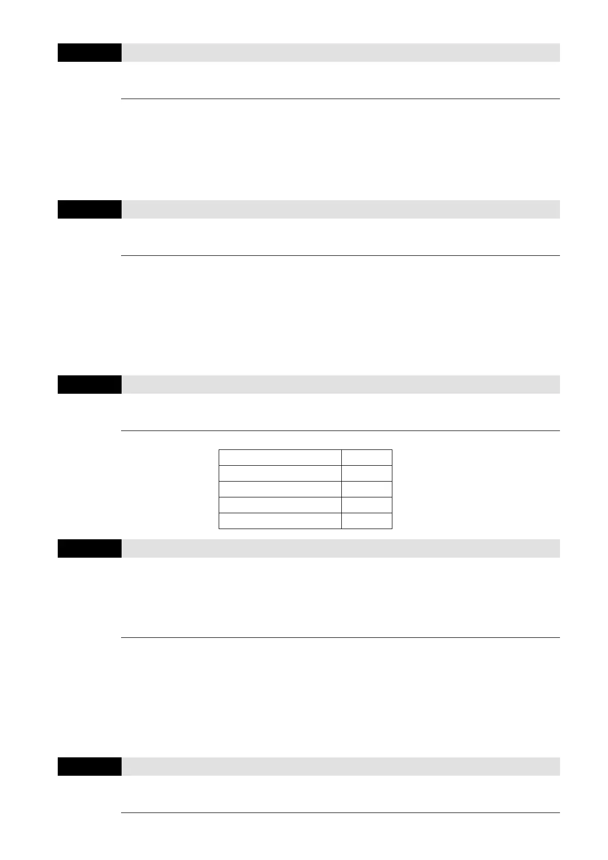
Corresponding versions for reference:
PG02U 21.XX
PG01U 31.XX
PG01O / PG01L 11.XX
PG02O / PG02L 14.XX
PG01R 41.XX
10-47
PG1 Pulse Imputation Scaling Factor
Default: 0
Settings
0: x1
1: x2
2: x4
3: x8
Use Pr.10-47 to set interpolation magnification of the PG1 Sin/Cos signal. After the interpolation
is finished, the encoder PPR (Pulses per Revolution) = Pr.10-01 ×2
Pr.10-47
× 4. The larger the
interpolation magnification, the more accurate the positioning.
Example:
When Pr.10-01 = 128 and Pr.10-47 = 0, PPR= 128 × 2
0
× 4 (four-time frequency) = 1024.
When Pr.10-01 = 128 and Pr.10-47 = 3, PPR= 128 × 2
3
× 4 (four-time frequency) = 8192.
10-49
Zero Voltage Time during Start-up
Default: 0.000
Settings 0.000–60.000 sec.