12 Descriptions of Parameter Settings | VFD-ED
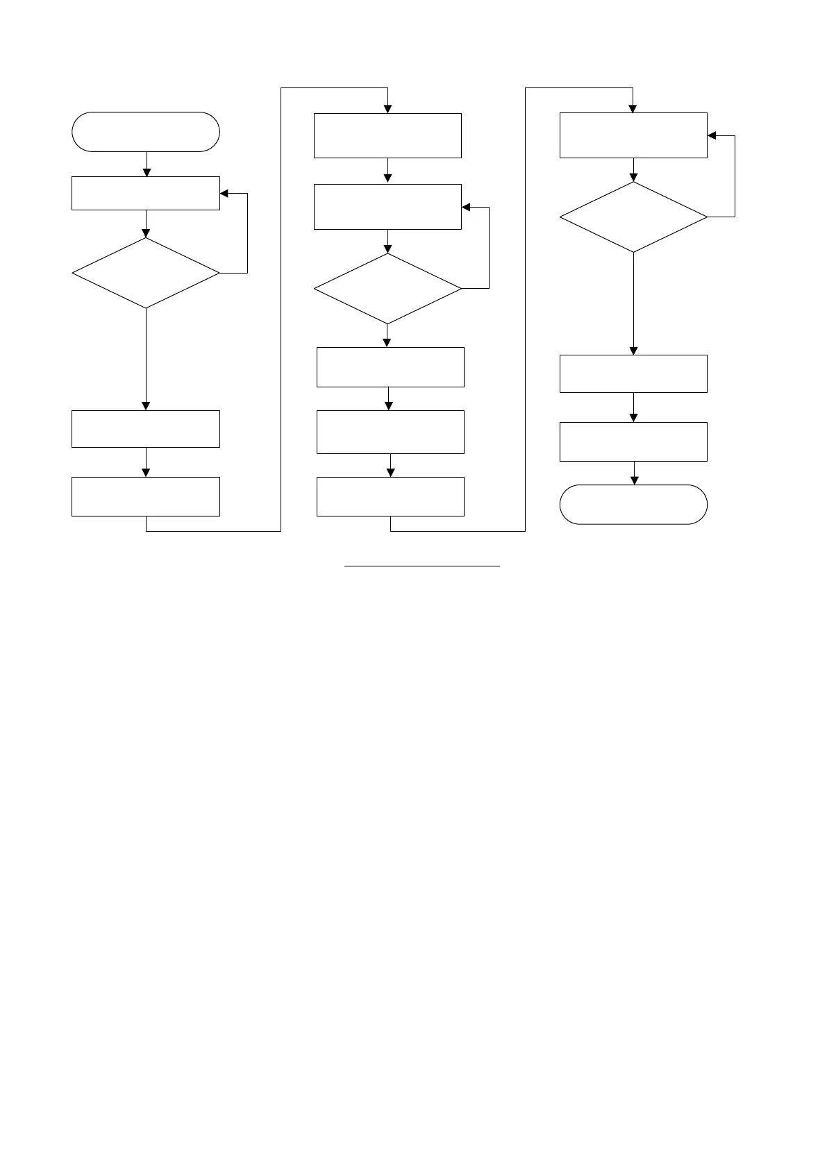
EPS Flow Chart (Battery)
The steps to set battery as EPS are as follows:
1. Set MI = 54 (Power failure signal)
2. Set MI = 43 (EPS function)
3. Set MO = 49 (Emergency power mode action)
4. Set Pr.06-46 = EPS mode selection
5. Set Pr.06-29 = Emergency power voltage running
6. Set Pr.06-48 = Emergency power capacity running
7. Set Pr.06-47 = Power generation direction search time
8. Set Pr.06-68 = Detecting level of power factor at the direction of power generation
9. Set Pr.06-71 = MO enables UPS delay time
10. Set Pr.06-72 = MO disables UPS delay time
NOTE: When using battery as EPS in an elevator system, auxiliary contact of the contactor should be used to
judge whether to cut off the power and notify the drive.
Mains power outage
Pr.06-71
Delay time (sec.)
UPS is ON
MO=49
is ON
UPS is OFF
Magnetic Contactor
MI =54
Check if
power is off
YES
NO
The host sends [EPS
Enable] to [MI=43]
MI =43
Check
Enable
NO
The elevator
reaches the level
Disables FWD/REV
commands
Sends FWD/REV
commands
The host sends [EPS
Disable] to [MI=43]
MI =43
Check
Disable
NO
Pr.06-72
Delay time (sec.)
MO=49
is OFF
 Loading...