Chapter 6 Optional Accessories | VFD-ED
Installation Precaution
Install the zero phase reactor at the drive’s output terminal (U/T1, V/T2, W/T3). After the zero phase
reactor is installed, it reduces the electromagnetic radiation and load stress emitted by the wiring of the
frequency converter. The number of zero phase reactors required for the drive depends on the wiring
length and the drive voltage.
The normal operating temperature of the zero phase reactor should be lower than 85°C (176°F).
However, when the zero phase reactor is saturated, its temperature may exceed 85°C (176°F). In this
case, increase the number of zero phase reactors to avoid saturation. The following are reasons that
might cause saturation of the zero phase reactors: the drive wiring is too long; the drive has several sets
of loads; the wiring is in parallel; or the drive uses high capacitance wiring. If the temperature of the zero
phase reactor exceeds 85°C (176°F) during the operation of the drive, increase the number of zero
phase reactors.
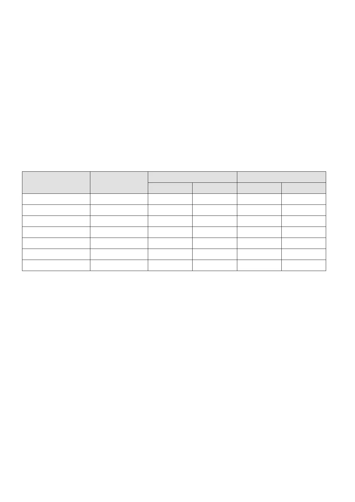
Recommended maximum wiring gauge when installing zero phase reactor:
Zero Phase Reactor
Model No.
Max. Wire Gauge or
LUG width
Max. Wire Gauge AWG (1 C*3) Max. Wire Gauge AWG (4 C*1)
75°C 90°C 75°C 90°C
RF008X00A 13 MM 3 AWG 1 AWG 3 AWG 1 AWG
RF004X00A 16 MM 1 AWG 2/0 AWG 1 AWG 1/0 AWG
RF002X00A 36 MM 600 MCM 600 MCM 1 AWG 1/0 AWG
RF300X00A 73 MM 650 MCM 650 MCM 300 MCM 300 MCM
T60006L2040W453 11 MM 9 AWG 4 AWG 6 AWG 6 AWG
T60006L2050W565 16 MM 1 AWG 2/0 AWG 1 AWG 1/0 AWG
T60006L2160V066 57 MM 600 MCM 600 MCM 300 MCM 300 MCM
Table 6-37