Chapter 2 Wiring | VFD-VJ
2-2
of the terminal.
Please use the shield wire or tube for the power wiring and ground the two ends of the
shield wire or tube.
Damaged insulation of wiring may cause personal injury or damage to
circuits/equipment if it comes in contact with high voltage.
The AC motor drive, motor and wiring may cause interference. To prevent the
equipment damage, please take care of the erroneous actions of the surrounding
sensors and the equipment.
When the hybrid servo drive output terminals U/T1, V/T2, and W/T3 are connected to
the motor terminals U/T1, V/T2, and W/T3, respectively. To permanently reverse the
direction of motor rotation, switch over any of the two motor leads.
With long motor cables, high capacitive switching current peaks can cause over-current,
high leakage current or lower current readout accuracy. For longer motor cables, use an
AC output reactor.
VFD-VJ series doesn’t have built-in brake resistors, but brake resistor can be installed
for those occasions that use higher load inertia or frequent start/stop. Refer to Appendix
A-1 for details.
Make sure that the leads are connected correctly and the hybrid servo drive is properly
grounded to reduce noise and for safety.
To prevent lighting stroke and electric shock, use ground leads that comply with local
regulations. Keep them as short and thick as possible and have them properly
connected to the ground terminal on the hybrid servo drive.
Connect the peripheral braid sleeve of the pressure sensor to the grounding terminal
PE.
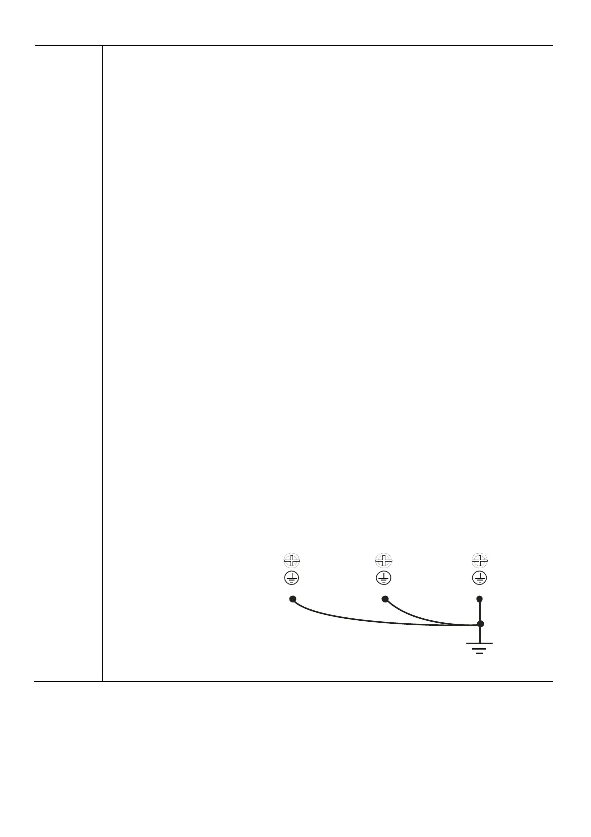
Multiple VFD-VJ units can be installed in one location. All the units should be grounded
directly to a common ground terminal, as shown in the figure below.
Ensure there are no ground loops.
Excellent
Grounding terminals
 Loading...