Chapter 2 Wiring | VFD-VJ
2-4
2-1 Description of Wiring
Users must connect wires according to the circuit diagrams on the following pages.
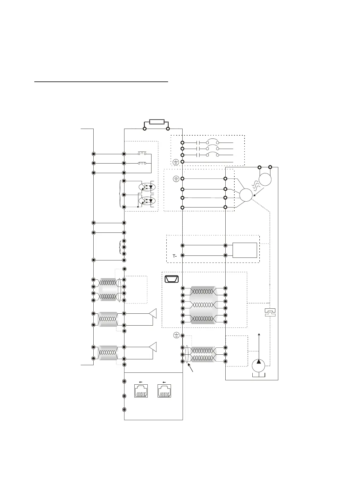
Standard wiring diagram of the VFD-VJ hybrid servo drive in factory
Wiring Diagram and Corresponding Models:
VFD300VL23C-J, VFD370VL23C-J,
VFD450VL43C-J, VFD550VL43C-J, VFD750VL43C-J
RC
RA
RB
MO1
MO2
SON
RES
MI3
MI4
MI5
COM
PI
ACM
QI
ACM
Controller
L1
L2
L3
R
S
T
U
V
W
+V
-V
+24V
ACM
PS
AC
FAN
220V/ 380V
M
3~
U
V
W
MCM
AFM1
ACM
0~10 /2mA
V
DC
B1
B2
T+
AFM2
ACM
-10 ~ +10
VV
DC DC
KTY84/
PTC/ Temp.
Switch
R1
R2
S2
S4
S1
S3
14,16
13,15
5
4
7
9
Resolver
81
81SGND
SG+
SG-
Modbus/CAN
Pin1: CAN_H
Pin 2: CAN_L
Pin 4: SG-
Pin 5: SG+
Pin 3, 6: SGND
Pin 8: +15V
Pin 7: reserved
*1
*2
*3
PE
PE
Shielded
Cable
PE
PE
PE
Brake Resistor (must-have accessory)
Malf unct ion Indicat ors
Enable
Oil Pump
Reset
Output
Te r m i n a l s
Unused
A
i
r
b
l
o
w
i
n
g
d
i
r
e
c
t
i
o
n
Unused
Pressure
Command
Shielded
Cable
Flow
Command
Feedback
Signal
Feedback
Signal
Shielded
Cable
Analog
Input
Te r mi n a l s
Default setting:
Pressure Feedback
Only for output frequency
Shielded
Cable
Output
Pressure Sensor
Use a mag n etic r in g
Temperature
Protectons
 Loading...