2. Wiring
2-3
Note 1*
pplicable to the models of 22kW or below
(including 22kW models with internal brake unit)
+1
+2/B1
B2
Brake resistor (optional)
-
pplicable to the models of 30kW or above
(including 30kW models with optional internal
brake unit)
VFDB
+1
+2
-
Brake resistor
Brake Unit
+-
B1
B2
Note 2*
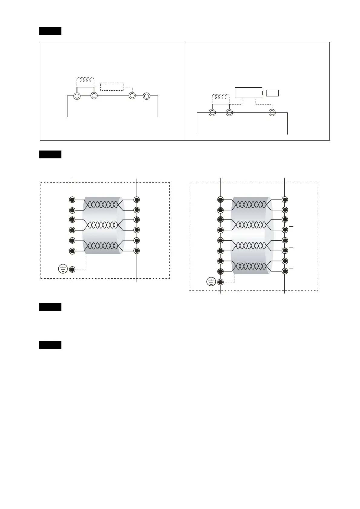
EMVJ-PG01R/PG02R
R1
R2
S2
S4
S1
S3
PG Card
14,16
13,15
5
4
7
9
Resolver
EMVJ-PG01U
Vp
GND
A
A
B
B
PG Card
14,16
13,15
5
4
7
9
Encoder
Z
Z
10
2
Note 3*
If the motor’s temperature protection switches are normally close type, please set the Parameter 03-04 to 4 first,
and then carry out the wiring. In this case, the drive may display the EF1 error message. Just clear the message.
Note 4*
Please select the R value in accordance with the thermistor specifications. The related trigger level
can be configured by the Parameters 02-08 to 02-10. If the thermistor of Model Number KTY84 is
used, select the R value as 2k (1/4W) ± 0.1%, and set the Parameter 02-11 with the value of 1.
 Loading...
