2. Wiring
2-13
-10V
AUI
+10V
internal circuit
AUI circuit
Resolution: 12 bits
Range: -10 ~ +10VDC
+10V Power supply for configuration
Power supply for analog configuration +10Vdc 20mA
(variable resistance 3~5k)
+24V
Power supply terminal for the
pressure sensor
Power supply for the pressure sensor +24Vdc 100mA
AFM
AFM
ACM
Impedance: 16.9k (voltage output)
Output current: 20mA max
Resolution: 0 – 10V for the maximum operating
frequency
Range: 0 – 10V
Function Setting: Parameter 00-05
ACM
Common ground for analog
control signals
Common ground terminal for analog control signals
* Specifications of analog control signal wire: 18 AWG (0.75 mm
2
), with shielded twisted pair
Analog Input Terminals (PO, PI, QI, AUI, ACM)
; The maximum input voltage of PI, PO, and QI cannot exceed +12V and no more than +/-12V for
AUI. Otherwise, the analog input function may become ineffective.
; Analog input signals are easily affected by external noise. Use shielded wiring and keep it as short
as possible (<20m) with proper grounding. If the noise is inductive, connecting the shield to
terminal ACM can bring improvement.
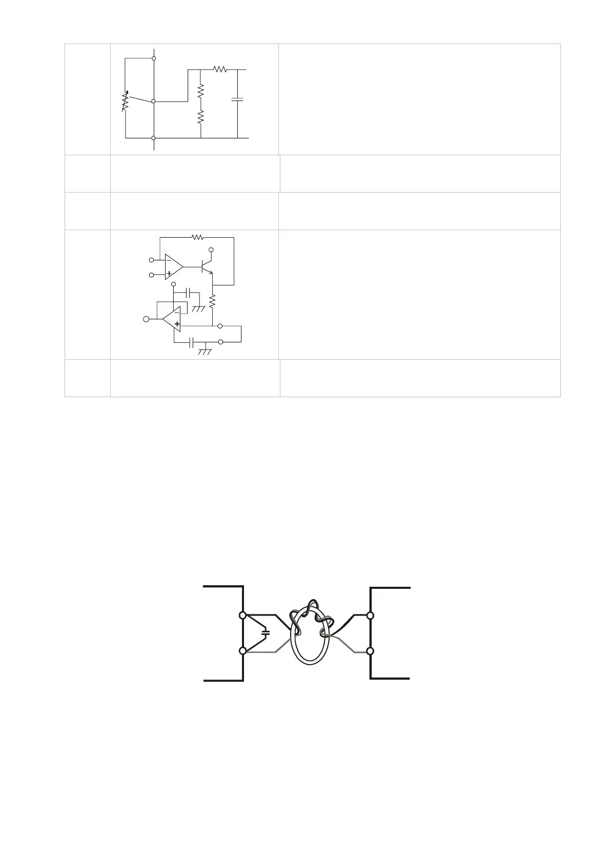
; If the analog input signals(pressure sensor) are affected by noise from the Hybrid servo drive,
please connect a capacitor and ferrite core as indicated in the following diagrams:
ferrite core
C
PO
ACM
-V
Output
wind each wires 3 times or more around the core
Transistor Output Terminals (MO1, MO2, MCM)
; Make sure to connect the digital outputs to the right polarity.
; When connecting a relay to the digital outputs connect a surge absorber across the coil and check
the polarity.
 Loading...
