Chapter 1. Description of Hybrid Servo Drives I VFD-VJ
1-6
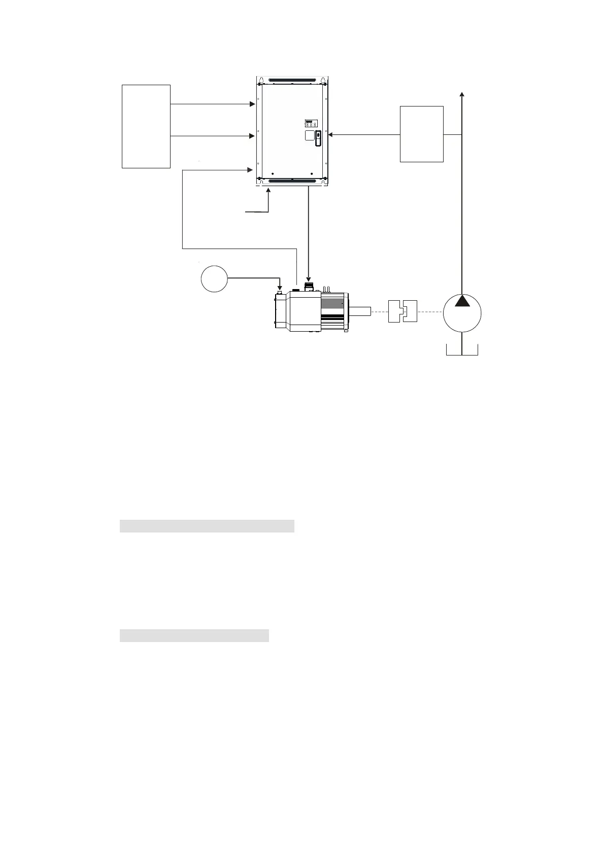
1-3 Overview of Hybrid Servo Systems
Injector
Controller
台达
油电伺服
变频器
Flow Rate Command
(0~10V/ Modbus/CAN)
Pressure Command
(0~10/Modbus/CAN)
RST
Power
Term inals
U V W
AC
FAN
220V/380V
UVW
Delta
Hybrid
Servo
Drive
Pressure
Feedback
(0 10~V,
adjustable by
parameters)
Pressure
Sensor
Encoder Signal
Oil
Pump
1-3-1 Selection of Hybrid Servo Drives and Motors
Due to the differences in the hydraulic system in practical applications, the following choice of
drives and motors is provided as a reference.
In the following example, a flow of 64L/min and maximum holding pressure of 175Bar are
used.
1. Pump Displacement per Revolution
Based on the maximum flow of the system (L/min), the pump displacement per revolution
(cc/rev) can be calculated.
Example: If the maximum flow of the system is 64L/min and the highest rotation speed of
the motor is 2000rpm, the displacement per revolution would be 64/2000*1000
= 32 cc/rev.
2. Maximum Torque of the Motor
Based on the maximum pressure (Mpa) and pump displacement per revolution (cc/rev),
the maximum torque can be calculated.
Example: If the required maximum pressure is 17.5 Mpa and pump displacement per
revolution is 32cc/rev, the maximum torque would be 17.5*32*1.3/ (2*pi) = 116
N-m, where the factor 1.3 is used to compensate the total loss in the system.
 Loading...
