Chapter 2. Wiring | VFD-VJ
2-23
Terminal Features Factory Setting (NPN Mode)
Difference
between
VJ-A and
VJ-B
SON Run-Stop
Terminal SON-COM: ON for Running; OFF for
Stop
EMG External error input External error input
RES Reset from error Reset from error
REV TBA TBA
New
terminal
MI3 Multi-function input selection 3
Configured as no function in factory
When it is ON, the input voltage is 24V
DC
(Max:
30V
DC
) and then input impedance is 3.75kΩ;
when it is OFF, the tolerable leakage current is
10μA.
MI4 Multi-function input selection 4
MI5 Multi-function input selection 5
COM
Common ground (Sink) for digital
control signals
Common ground for multi-function input
terminals
RA Error terminal 1 (Relay N.O. a)
Resistive load
5A(N.O.)/3A(N.C.) 240VAC
5A(N.O.)/3A(N.C.) 24VDC
Inductive load
1.5A(N.O.)/0.5A(N.C.) 240VAC
1.5A(N.O.)/0.5A(N.C.) 24VDC
RB Error terminal 1 (Relay N.C. b)
RC
Command contact for multi-function
output terminals (Relay)
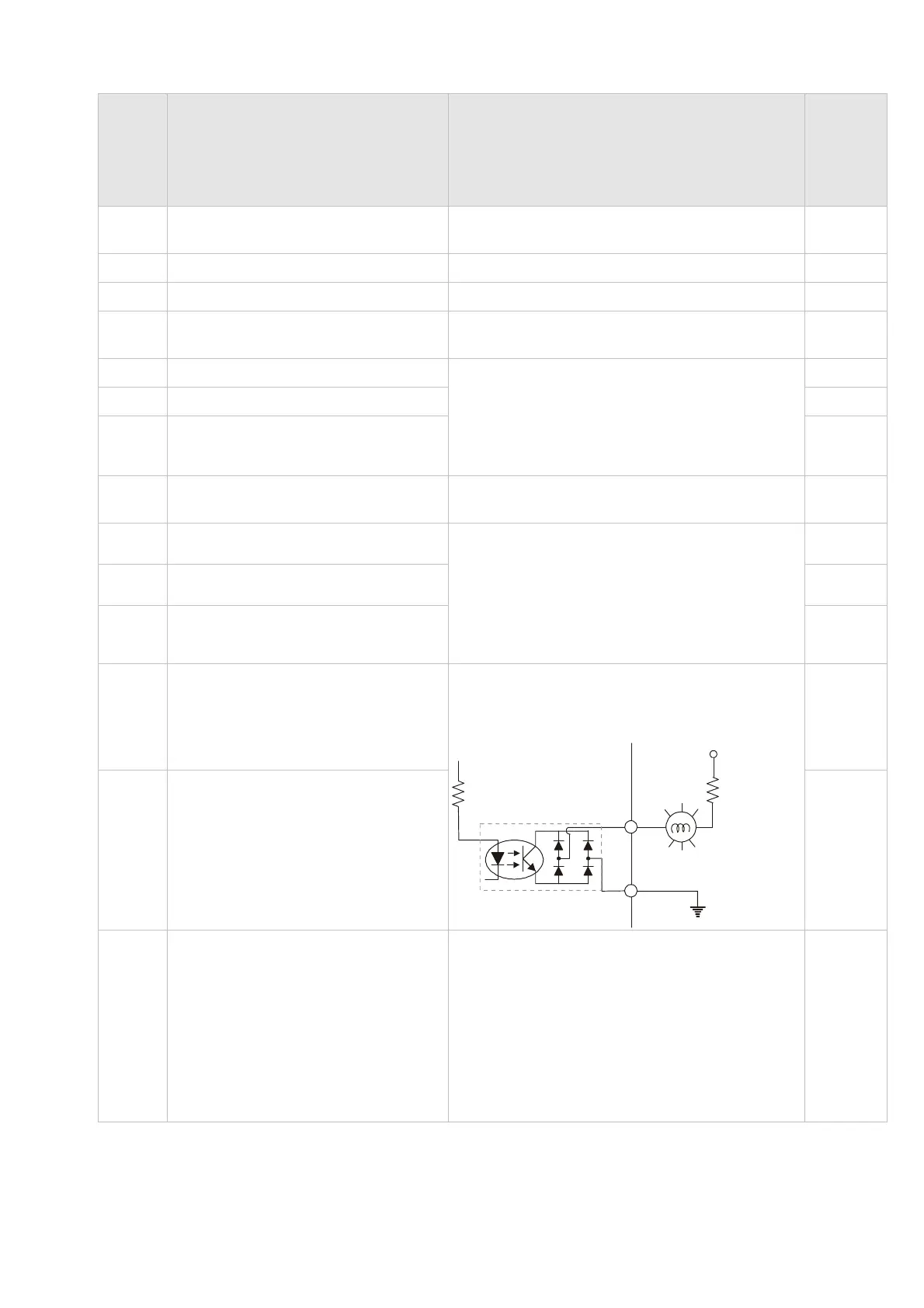
MO1
Multi-function output terminal 1
(photocoupler)
The hybrid servo drive sends various
monitoring signals by means of open-collector
configuration.
MO1
~
MO2
internal circuit
MCM
Max: 48Vdc/50mA
MO2
Multi-function output terminal 2
(photocoupler)
MCM
Common ground for Multi-function
output terminal (photocoupler)
Max 48V
DC
50mA
 Loading...
