Chapter 12 Description of Parameter SettingsC2000-HS
12.1-06-24
Low Current Action
Default: 0
Settings 0: No function
1: Warn and coast to stop
2: Warn and ramp to stop by the 2
nd
deceleration time
3: Warn and continue operation
The drive operates according to the setting for Pr. 06-73 when the output current is lower than the
setting for Pr. 06-71 and when the time of the low current exceeds the detection time for Pr. 06-72.
Use this parameter with the external multi-function output terminal 44 (for low current output).
The low current detection function does not execute when drive is in sleep or standby status.
Sets Pr. 06-71 low current level according to the drive’s rated current, the equation is Pr. 00-01
(drive’s rated current) x Pr. 06-71 (low current setting level) % = low current detection level (A).
The drive changes the setting for Pr. 00-01 (rated current) according to the setting for Pr. 00-16
(load selection).
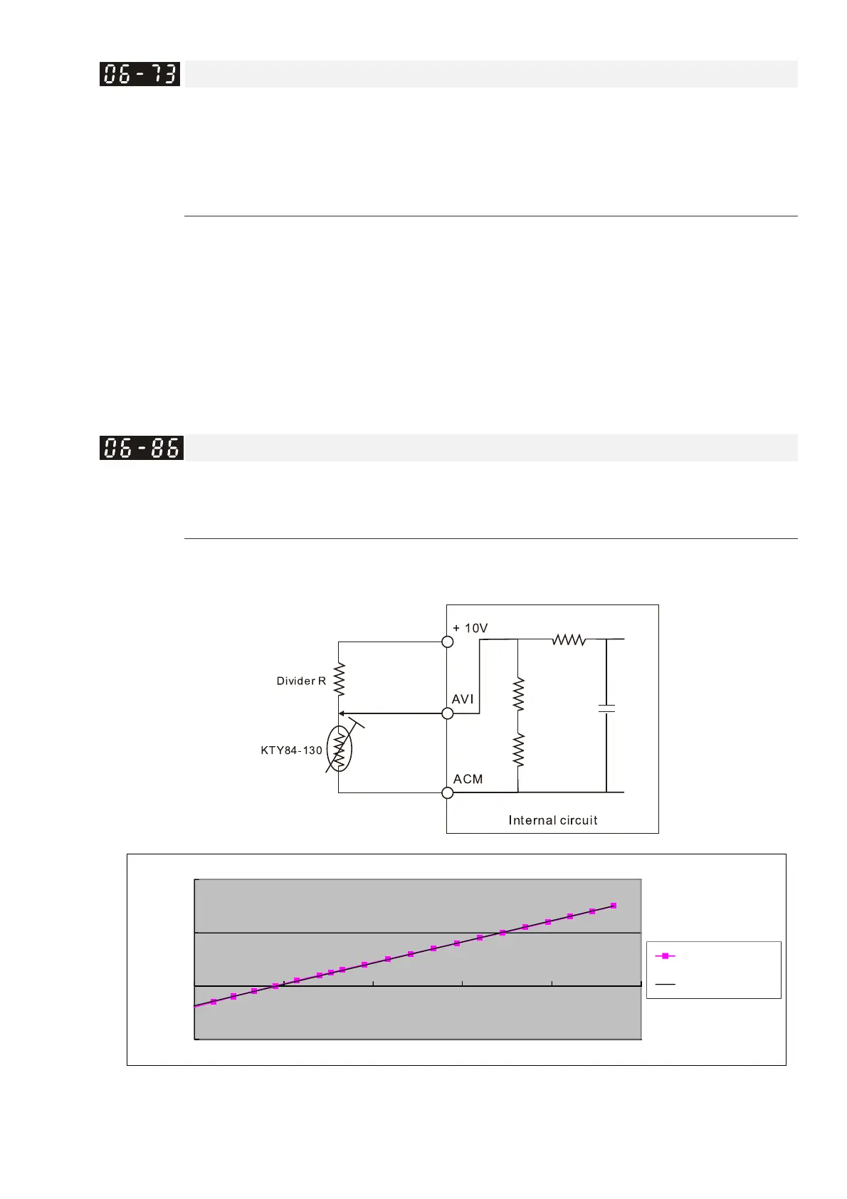
PTC Type
Default: 0
Settings 0: PTC
1: KTY84-130
When using KTY84-130, a divider resistance (2kΩ, power > 1/4W, ±0.1%) is needed.
Wiring diagram is as below:
When the temperature exceeds the setting level, an oH3 error occurs to the drive. Reset
conditions: when the temperature is below the trigger level -5ºC, the oH3 error is cleared.
y = 79.717x
-
156.64
-100
0
100
200
1.50 2.00 2.50 3.00 3.50 4.00
T
(°C)
nalog voltage (V)
C2000-HS / KTY84-130 Temperature and voltage diagram
C2000-HS
Linear (C2000-HS)
 Loading...