4-28
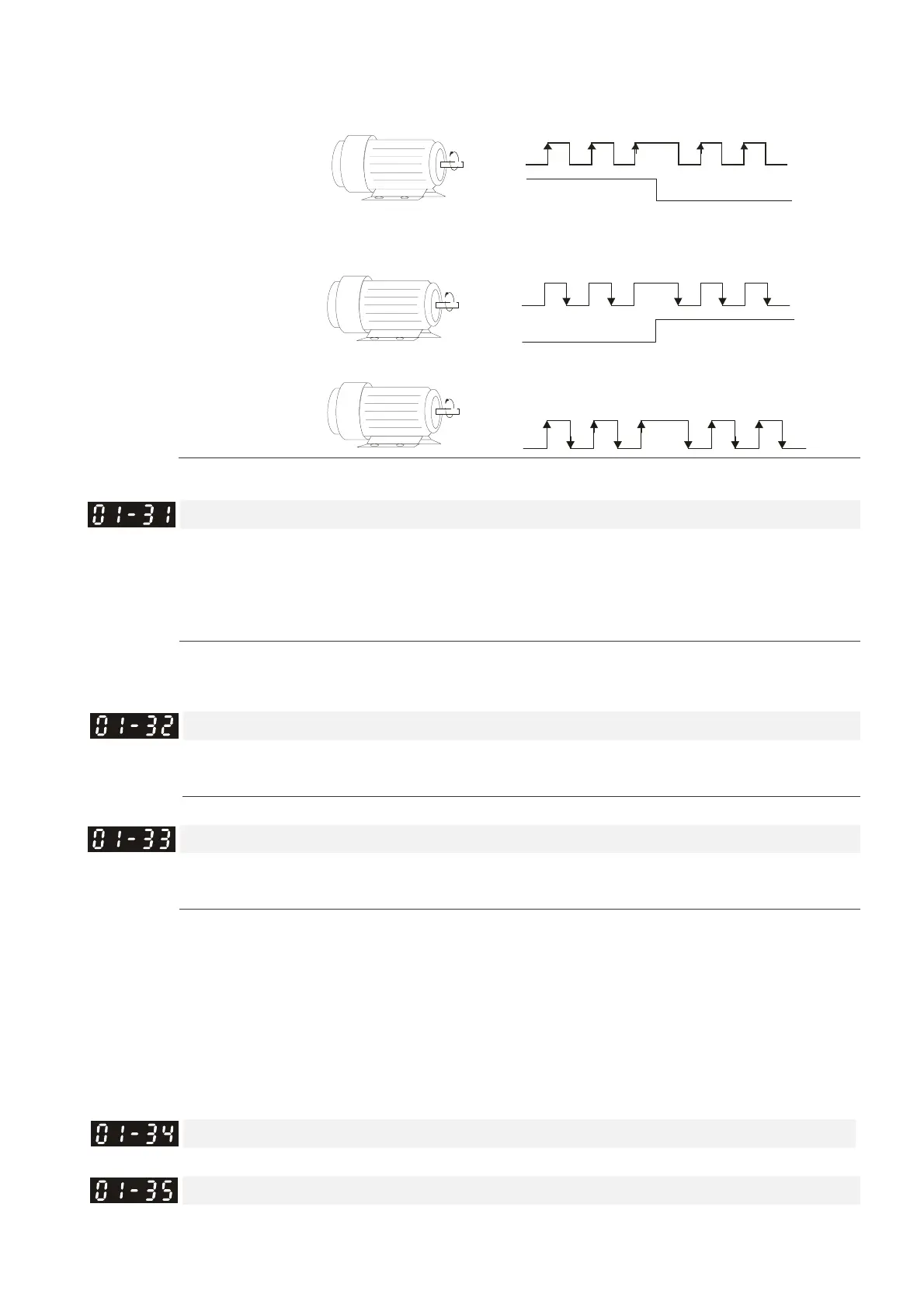
3: Phase A is a pulse input and phase B is a direction input. (low
input=reverse direction, high input=forward direction).
Forward
Rotation
Forward Rotation Reverse Rotation
A
4: Phase A is a pulse input and phase B is a direction input. (low
input=forward direction, high input=reverse direction).
Forward
Rotation
Forward Rotation
Reverse Rotation
A
B
5: Single-phase input
Forward
Rotation
A
Enter the correct setting for the pulse type is helpful in controlling the stability.
System control
Control mode FOCPG FOCPM
Factory default: 1
Settings 0: No function
1: ASR automatic tuning
2: Estimation of inertia
If the setting value is 1: The speed control gain is determined by Parameters 00-10
If the setting value is 2: The system inertia is estimated. Please refer to descriptions in Chapter 3
a
Unity value of the system inertia
Control mode FOCPG FOCPM
Factory default: 400
Settings 1~65535 (256 = 1 per unit)
Carrier frequency
Control mode FOCPG FOCPM
Factory default: 5
Settings 5 kHz; 10kHz
When this parameter is configured, please re-start the Hybrid servo drive.
The carrier frequency of the PWM output has a significant influence on the electromagnetic noise
of the motor. The heat dissipation of the Hybrid servo drive and the interference from the
environment may also affect the noise. Therefore, if the ambient noise is greater than the motor
noise, reducing the carrier frequency of the drive may have the benefits of reducing a temperature
rise; if the carrier frequency is high, even if a quiet operation is obtained, the overall wiring and
interference control should be taken into consideration.
a
Reserved
Motor ID
Control mode FOCPG FOCPM
Factory default: 0
 Loading...