12
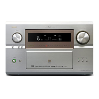
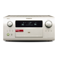
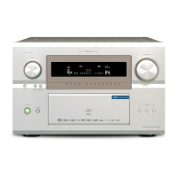
AVR-4802/AVC-A11SR
ADJUSTMENT
Audio Section
Idling Current (1U-3356-1, 2)
Required measurement equipment : DC Voltmeter
Preparation
(1) Avoid direct blow from an air conditioner or an electric fan, and adjust the unit at normal room tempereture 15 °C ~ 30 °C
(59 °F ~ 86 °F).
(2) Presetting
POWER (Power source switch) → OFF
SPEAKER (Speaker terminal) → No load (Do not connect speaker, dummy resistor, etc.)
Adjustment
(1) Remove top cover and set VR101, VR301, VR401 on 1U-3356-1 (Power Amp L unit), VR102, VR202, VR302, VR402 on
1U-3356-2 (Power Amp. R Unit) at fully counterclockwise (
) position.
(2) Connect DC Voltmeter to test points (FRONT-Lch: TP101, FRONT-Rch: TP102, CENTER ch: TP202, SURROUND-Lch:
TP301, SURROUND-Rch: TP302, SURROUND BACK-Lch: TP401, SURROUND BACK-Rch: TP402).
(3) Connect power cord to AC Line, and turn power switch "ON".
(4) Presetting. MASTER VOLUME : "---" counterclockwise (
min.)
MODE : 5CH/7CH STEREO
FUNCTION : CD
(5) Within 2 minutes after the power on, turn VR101 clockwise (
) to adjust the TEST POINT voltage to 2 mV ±0.5 mV DC.
(6) After 10 minutes from the preset above, turn VR101 to set the voltage to 2 mV ±0.5 mV DC.
(7) Adjust the Variable Resistors of other channels in the same way.
1U-3356-1
VR402
TP402
1U-3356-2
Power Trans
VR302
TP302
VR102
TP102
VR401
TP401
VR301
TP301
VR101
TP101
DC Voltmeter
VR202
TP202
w
w
w
.
x
i
a
o
y
u
1
6
3
.
c
o
m
Q
Q
3
7
6
3
1
5
1
5
0
9
9
2
8
9
4
2
9
8
T
E
L
1
3
9
4
2
2
9
6
5
1
3
9
9
2
8
9
4
2
9
8
0
5
1
5
1
3
6
7
3
Q
Q
TEL 13942296513 QQ 376315150 892498299
TEL 13942296513 QQ 376315150 892498299
http://www.xiaoyu163.com
http://www.xiaoyu163.com