73
ENGLISH
Basic version Advanced versionSimple version Information
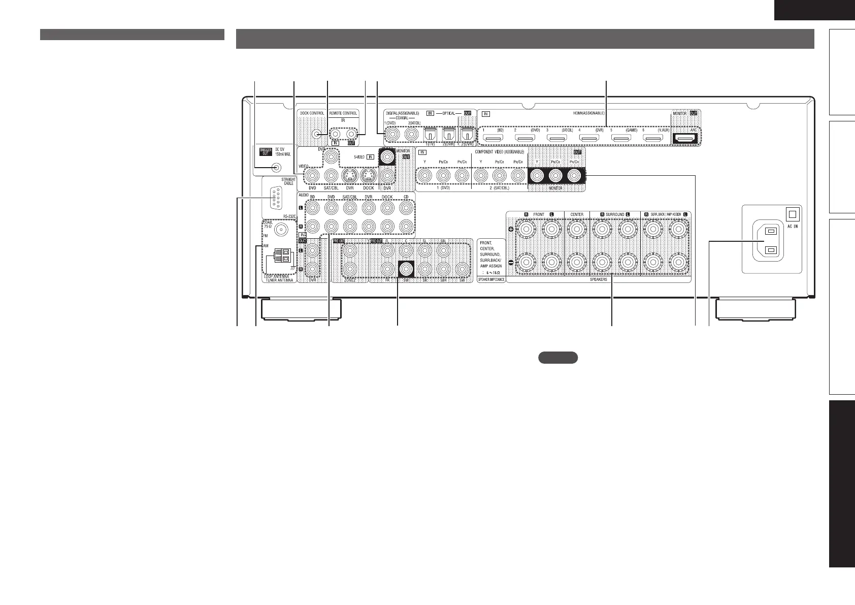
Rear panel
See the page indicated in parentheses ( ).
wq e r yt
ioQ1 Q0
Q2
Q3
u
q RS-232C connector ·································································· (20)
w FM/AM antenna terminals ····················································· (19)
e Analog audio connectors ·················································(16 – 20)
r PRE OUT connectors ··············································(5, 34 – 36, 42)
t Speaker terminals ························································(5, 34 – 36)
y COMPONENT VIDEO connectors ····································· (15, 16)
u AC inlet (AC IN) ·········································································· (5)
i HDMI connectors ····································································· (14)
o Digital audio connectors ··················································(15 – 17)
Q0 REMOTE CONTROL jacks ······················································· (20)
Q1 DOCK CONTROL jack ······························································ (18)
Q2 S-VIDEO/VIDEO connectors ············································(15 – 18)
Q3 TRIGGER OUT jack ·································································· (20)
NOTE
Do not touch the inner pins of the connectors on the rear panel.
Electrostatic discharge may cause permanent damage to the unit.
Q6 Tuner reception mode indicators
These light according to the reception conditions
when the input source is set to “TUNER”.
STEREO : In the FM mode, this light when
receiving analog stereo broadcasts.
TUNED : Lights when the broadcast is properly
tuned in.
AUTO : This light when in the auto tuning mode.
RDS: This light when receiving RDS broadcasts.
Q7 Recording output source indicator
This lights when the REC OUT mode is selected.
Q8 Decoder indicators
These light when the respective decoders are
operating.
Display
 Loading...