J
jennifer17Jul 26, 2025
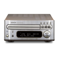
What to do if the VFD is not lit on my Denon RCD-M40 Car Receiver?
- MMike PayneJul 26, 2025
If the VFD (Vacuum Fluorescent Display) on your Denon Car Receiver is not lit, several components need inspection. Start by checking the power supply voltages for both the system and the VFD itself. Also, verify the reset signal for both the system and the VFD. Further troubleshooting includes checking the oscillation waveform, the POWER ON signal, and the drive signals for the VFD. Soldering and individual parts should also be checked.