18
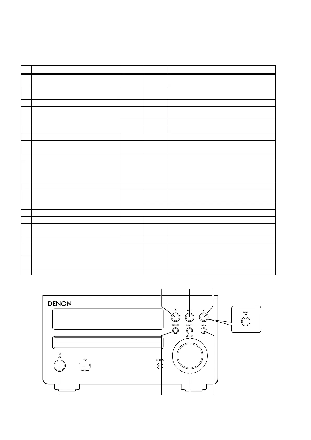
SPECIAL MODE
Special mode setting button
※ No.1 - 6, 8 : While holding down buttons "
A
" and "
B
" simultaneously, insert the AC plug into the wall outlet to turn on
the power.
※ No.7 : Perform this operation while the power is on.
No. Mode Button A Button B Descriptions
1 Version Display Mode
2 8
/–
Displays the version of rmware such as the main rm-
ware. (See page 19)
2 Display check mode
5 X
Lights and unlights each segment repeatedly.
(See page 19)
3 Initialize (cold start) SOURCE
8
/– Initializes the data. (See page 19)
4 CD test mode SOURCE
X
Servo adjustment. Displaying the adjustment values and
laser current. (See page 20)
4-1 Disc mounting
5
– For executing each CD mode.
4-2 Servo check
1
/
3
– Checks each servo.
4-3 Pickup movement
8
/– or +/
9
Moves the pickup to the inner or outer circumference.
4-4 Stop
2
–
Stops playback operations and servos and loads the
automatic adjustment values.
4-5 All servo on SOURCE – Turns all servos on and performs automatic adjustment.
4-6 Display adjustment values ↑ –
Displays the following adjustment values.
FOCUS BALANCE, FOCUS GAIN, TRACKING BALANCE,
TRACKING GAIN, FOCUS OFFSET, TRACKING OFFSET,
RFRP
4-7 Displaying the laser current
2
– Indicates the present laser current.
5 CD heat Run mode
2
+/
9
Executes each heat run mode.
(See page 23)
5-1 Normal heat run mode
1
/
3
– Executes normal heat run mode.
5-2 Chucking mode
2
– Executes chucking mode.
5-3 Error display – Displays the error code.
6 Accumulated laser on time display mode
2 X
Indicates the accumulated laser on time.
(See page 25)
6-1 Resetting the count value
1
/
3
– The setting values are initialized.
7 Update MAIN u-COM
X 2
Updates the microprocessor.
(See page 25)
8 Protection history display mode SOURCE +/
9
Displays the protection occurrence history.
(See page 26)
8-1 Resetting the protection history
1
/
3
– Resetting the protection history.
RCD-M40DAB
51
32
X
9
8