EasyManua.ls Logo

Denon RCD-M40 - 5. POWER and CONNECT PCB; 6. MCU PCB; 7. SPEAKER PCB; 8. TRANS

Denon RCD-M40
89 pages
Print Icon
To Next Page IconTo Next Page
To Previous Page IconTo Previous Page
Loading...
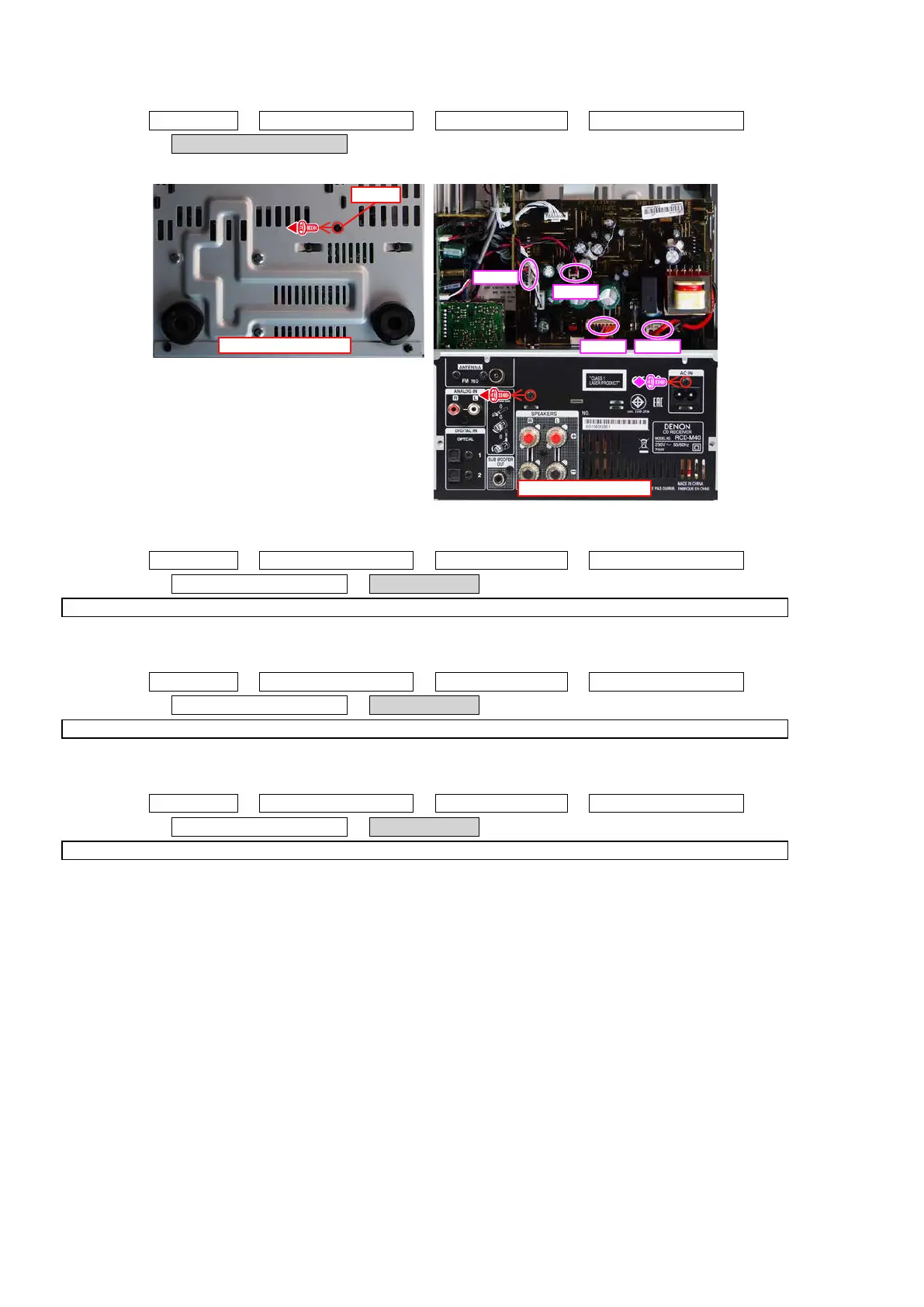
5. POWER and CONNECT PCB
Proceeding : TOP COVER
→
LOADER PANEL ASSY
→
FRONT PANEL ASSY
→
HEAT SINK SUB ASSY
→
POWER and CONNECT PCB
(1) Remove the screws. Remove the connector wires.
6. MCU PCB
Proceeding : TOP COVER
→
LOADER PANEL ASSY
→
FRONT PANEL ASSY
→
HEAT SINK SUB ASSY
→
POWER and CONNECT PCB
→
MCU PCB
See "EXPLODED VIEW" for instructions on removing the MCU PCB.
7. SPEAKER PCB
Proceeding : TOP COVER
→
LOADER PANEL ASSY
→
FRONT PANEL ASSY
→
HEAT SINK SUB ASSY
→
POWER and CONNECT PCB
→
SPEAKER PCB
See "EXPLODED VIEW" for instructions on removing the SPEAKER PCB.
8. TRANS
Proceeding : TOP COVER
→
LOADER PANEL ASSY
→
FRONT PANEL ASSY
→
HEAT SINK SUB ASSY
→
POWER and CONNECT PCB
→
TRANS
See "EXPLODED VIEW" for instructions on removing the transformer (TRANS).
View from the bottom
Shooting direction: A
STEP 1
CW01
CW02
CN99
CN94
16