127
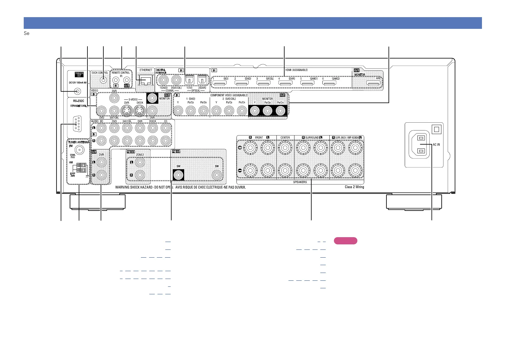
Rear panel
See the page indicated in parentheses ( ).
i
q w
e r t y
o u
Q4 Q3 Q1Q2 Q0
q RS-232C connector ·································································· (18)
w FM/AM antenna terminals ····················································· (16)
e Analog audio connectors ······································ (11, 12, 13, 16)
r PRE OUT connectors
························································ (C 6, 59, 60, 61, 62, 63, 64)
t Speaker terminals ························· (C 6, 59, 60, 61, 62, 63, 64)
y AC inlet (AC IN) ·································································· (C 5)
u COMPONENT VIDEO connectors ······························· (10, 11, 12)
i HDMI connectors ··························································· (C 3, 8)
o Digital audio connectors ······································· (10, 11, 12, 13)
Q0 ETHERNET connector ····························································· (17)
Q1 REMOTE CONTROL jacks ······················································· (18)
Q2 DOCK CONTROL jack ······························································ (14)
Q3 S-VIDEO/VIDEO connectors ··························· (10, 11, 12, 13, 14)
Q4 TRIGGER OUT jack ·································································· (18)
NOTE
Do not touch the inner pins of the connectors on the rear panel.
Electrostatic discharge may cause permanent damage to the unit.
 Loading...