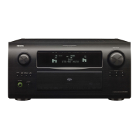
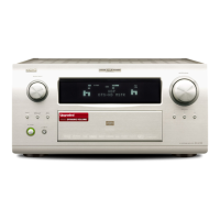
EasyManuals Logo

Denon AVR-4208 User Manual

Denon AVR-4208
283 pages
To Next Page IconTo Next Page
To Previous Page IconTo Previous Page
Page #6 background imageLoading...
Page #6 background image
6
ENGLISH
SPEAKER SYSTEMS
PRE OUT
DVD TV MONITOR
YP
B/CB PR/CRYPB/CB PR/CRYPB/CB PR/CRYPB/CB PR/CR
COMPONENT
VIDEO
DBS/
SAT
FRONT
CENTER
FR FL
SW C
SR SL
SBR SBL
SURROUND
-A
R
R
SURROUND
-B
DVD VDP TV DBS/
SAT
V. AUX VCR-1 VCR-2 VCR-3 VCR-1 VCR-2 VCR-3
S-VIDEO
VIDEO
1-
MONITOR
-2
R
S. BACK
R
IN
IN IN IN OUT
OUT OUT
OUT
S-VIDEO
IN
S-VIDEO
OUT
S-VIDEO
IN OUT
S-VIDEO
IN OUT
S-VIDEO
B
LD player, CDV player, etc.
Monitor TV
Video deck 2
Video deck 1
TV or satellite broadcast tuner
Connecting a video disc player (VDP)
Connecting a monitor TV
Connecting the video decks
Connecting a TV, DBS/SAT tuner
VDP
Connect the video disc player’s S-Video output jack to the
S-VIDEO VDP IN jack using an S-Video connection cord.
A DVD player can be connected to the DVD jacks in the
same way.
It is also possible to connect a video disc player, DVD player,
video camcorder, game machine, etc., to the V.AUX jacks.
MONITOR OUT
Connect the TV’s or DBS tuner’s S video input (S-VIDEO
INPUT) to the MONITOR OUT-1 jack using a S
jack connection cord.
The monitor TV can also be connected in the same way to
the S-VIDEO MONITOR OUT-2 jack. Note, however, that
the AVC-A11SR’s on-screen display signals are not output
from this jack.
S-VIDEO
Connect the TV’s or DBS/SAT tuner’s S video output jack (S-VIDEO
OUTPUT) to the TV, DBS/SAT IN jack using a S jack
connection cord.
S-VIDEO
Connect the video deck’s S output jack (S-OUT) to the VCR-1 IN
jack and the video deck’s S input jack (S-IN) to the VCR-1 OUT jack
using S jack connection cords.
Connect the video deck’s S output jack (S-OUT) to the VCR-2 IN
jack and the video deck’s S input jack (S-IN) to the VCR-2 OUT jack
using S jack connection cords.
Connect the another video deck to the VCR-3 jacks in the same way.
S-VIDEO
S-VIDEO
S-VIDEO
S-VIDEO
Connect the components’ audio inputs and
outputs as described on page 5.
NOTES:
The on-screen display signals are not output from the video signal MONITOR OUT-2 (yellow) or S-Video
signal MONITOR OUT-2 jack.
The MONITOR OUT-2 output switches together with the input function selected with the REC/MULTI
button. To use as the monitor output, set “SOURCE” as the REC/MULTI input function.
Connecting a video component equipped with S-Video jacks
When making connections, also refer to the operating instructions of the other components.
A note on the S input jacks
The input selectors for the S inputs and pin jack inputs work in conjunction with each other.
Precaution when using S-jacks
This unit’s S-jacks (input and output) and video pin jacks (input and output) have independent circuit structures,
so that video signals input from the S-jacks are only output from the S-jack outputs and video signals input
from the pin jacks are only output from the pin jack outputs.
When connecting this unit with equipment that is equipped with S-jacks, keep the above point in mind and
make connections according to the equipment’s instruction manuals.
DVD TV MONITOR
YP
B/CB PR/CRYPB/CB PR/CRYPB/CB PR/CRYPB/CB PR/CR
COMPONENT
VIDEO
DBS/
SAT
DVD VDP TV DBS/
SAT
V. AUX VCR-1 VCR-2 VCR-3 VCR-1 VCR-2 VCR-3
S-VIDEO
1-
MONITOR
-2
IN
IN IN IN OUT
OUT OUT
SPEAKER SYSTEMS
FRONT
SURROUND
-A
L
L
SURROUND
B
PrPbY
B
B
VIDEO OUT
Pr
Y
Pb
COMPONENT
VIDEO IN
COMPONENT
DVD player
Monitor TV
Connecting a DVD player
Connecting a monitor TV
DVD IN jacks
Connect the DVD player’s color difference (component)
video output jacks (COMPONENT VIDEO OUTPUT) to the
COMPONENT DVD IN jack using 75 / ohms coaxial video pin-
plug cords.
In the same way, another video source with component
video outputs such as a DTV, DBS/SAT tuner, etc., can be
connected to the TV, DBS/SAT color difference (component)
video jacks.
MONITOR OUT jack
Connect the TV’s color difference (component) video
input jacks (COMPONENT VIDEO INPUT) to the
COMPONENT MONITOR OUT jack using 75 /ohms
coaxial video pin-plug cords.
The color difference input jacks may be indicated differently on some TVs,
monitors or video components (“Pr, Pb and Y”, “R-Y, B-Y and Y”, “Cr, Cb and
Y”, etc.). For details, carefully read the operating instructions included with
the TV or other component.
When making connections, also refer to the operating instructions of the other components.
The signals input to the color difference (component) video jacks are not output from the VIDEO output jack
(yellow) or the S-Video output jack. In addition, the video signals input to the VIDEO input (yellow) and S-Video
input jacks are not output to the color difference (component) video jacks.
The AVC-A11SR’s on-screen display signals are not output from the color difference (component) video output
jacks (MONITOR OUT).
Some video sources with component video outputs are labeled Y, Pb, Pr, or Y, Cb, Cr, or Y, R-Y, B-Y. These
terms all refer to component video color difference output.
Connecting a Video Component Equipped with Color Difference (Component
- Y, P
B
/C
B
, P
R
/C
R
) Video Jacks (DVD Player)

Table of Contents

Other manuals for Denon AVR-4208

Questions and Answers:

Question and Answer IconNeed help?

Do you have a question about the Denon AVR-4208 and is the answer not in the manual?

Denon AVR-4208 Specifications

General IconGeneral
BrandDenon
ModelAVR-4208
CategoryAmplifier
LanguageEnglish

Related product manuals