Explanatory Photos for DISASSEMBLY
• For the shooting direction of each photos used in this manual, see the photo below.
• A, B, C and D in the photo below indicate the shooting directions of photos.
• The photographs with no shooting direction indicated were taken from the top of the unit.
• Photos of AVR-S530BT E3 are used in this manual.
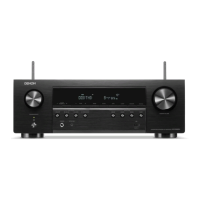
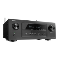
The viewpoint of each photograph
(Shooting direction : X) [View from the top]
↓Shooting direction: C↓
↑Shooting direction: D↑
↑Shooting direction: A↑
↓Shooting direction: B↓
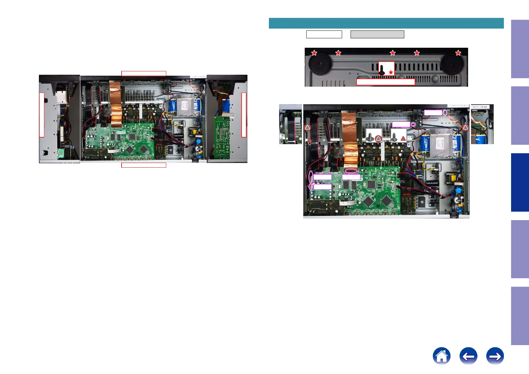
Proceeding : TOP COVER → FRONT PANEL ASSY
(1) Remove the screws.
(2) Remove the screws. Remove the connector. Remove the FFC.
1. FRONT PANEL ASSY
View from the bottom
x5
x2 x1
CN140
CN713
CN752
FFC
CN102
49
Caution in
servicing
Electrical Mechanical Repair Information Updating

 Loading...