Do you have a question about the Denon AVR-S910W and is the answer not in the manual?
Explains search and navigation features within the manual.
Guides on using Adobe Reader features like notes and magnification.
Warns about electric shock, burrs, parts usage, and wire arrangement.
Lists essential checks to ensure safety after servicing the unit.
Instructions for grounding human body and workbench for safe semiconductor handling.
Details technical specifications and physical dimensions for the AVR-X2200W model.
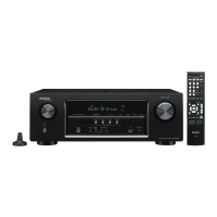
Details technical specifications and physical dimensions for the AVR-S910W model.
Cautions and procedures specific to servicing the AVR-X2200W unit.
Cautions and procedures specific to servicing the AVR-S910W unit.
Lists specific jigs required for PCB repair and how to order them.
Step-by-step instructions for disassembling the front panel assembly.
Step-by-step instructions for disassembling the radiator assembly.
Step-by-step instructions for disassembling HDMI, VIDEO, MAIN, SMPS PCBs and Transformer.
Explains how to enter special modes using buttons on the AVR-X2200W.
Explains how to enter special modes using buttons on the AVR-S910W.
Displays firmware version information for the unit.
Allows switching PANEL LOCK and REMOTE LOCK modes between ON and OFF.
Selects diagnostic modes like service path check or protection history.
Enables operation of only the desired AV receiver when multiple are used.
Allows power to be turned on without activating protection circuits.
Procedures for rebooting and initializing the CY920 unit.
Outlines procedures and software writing requirements after replacing key components.
Instructions for downloading and updating firmware via USB memory.
Guides for updating firmware via network using DPMS.
Details USB update error codes, their meanings, and remedies.
Details DPMS error codes, their meanings, and remedies.
Mode used to forcibly switch the unit to USB update mode when it cannot be recovered.
Procedure to follow if a "CY920 Error" message appears after PCB replacement.
Troubleshooting steps for issues related to the unit not powering on.
Troubleshooting steps for analog video input or component/HDMI output issues.
Troubleshooting for no picture or sound output when using HDMI to HDMI connection.
Guides to check audio output for analog, digital, and HDMI sources.
Troubleshooting steps for power amplifier issues related to no audio output.
Troubleshooting steps for analog audio issues, checking power supply and signal paths.
Troubleshooting steps for issues related to network connectivity.
Troubleshooting steps for Bluetooth connection problems.
Troubleshooting steps when the unit does not recognize a connected USB device.
Troubleshooting for no picture or sound output related to USB or digital signals.
Troubleshooting steps for issues related to the SMPS (Switch Mode Power Supply).
Describes the waveforms for DIR input, DIR output, and DAC input.
Block diagram illustrating the analog audio signal path.
Diagram showing the power supply distribution.
Illustrates the internal wiring connections between PCBs.
Shows the layout of printed wiring boards for key components.
Detailed circuit schematics for various sections like HDMI, CPU, DSP, etc.
Lists major semiconductors used in the unit, including pin functions.
Details pin functions and block diagram for the PCM9211 chip.
Details pin configuration and functions for the AD8195ACPZ chip.
Details pin description and block diagram for the W9864G6KH-5 chip.
Details pin functions and block diagram for the PCM1690 chip.
Details terminal functions and block diagram for the PCM5100 chip.
Details the pin assignments for the BD34704KS2 chip.
| Receiver type | Surround |
|---|---|
| Audio output channels | 7.2 channels |
| Power output per channel (1KHz@6 Ohm) | 185 W |
| Power output per channel (20-20KHz@8 Ohm) | - W |
| HDMI in | 8 |
| Composite video in | 2 |
| Digital audio coaxial in | 1 |
| Wi-Fi | Yes |
| AM band range | 520 - 1710 kHz |
| FM band range | 87.5 - 107.9 MHz |
| Supported radio bands | AM, FM |
| Internet radio services supported | Pandora, SIRIUS Internet Radio, Spotify |
| Optical drive included | No |
| Display | - |
| Product color | Black |
| Audio decoders | Dolby Surround, Dolby TrueHD |
| AC input voltage | 120 V |
| Power consumption (standby) | 0.1 W |
| Power consumption (typical) | 500 W |
| Audio formats supported | AAC, ALAC, FLAC, MP3, WAV, WMA |
| Depth | 337.82 mm |
|---|---|
| Width | 434.34 mm |
| Height | 167.64 mm |
| Weight | 9389 g |