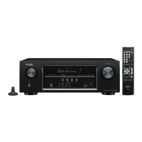
FRONT PANEL ASSY
See "DISASSEMBLY"
1. FRONT PANEL ASSY
and "EXPLODED VIEW"
FRONT HDMI PCB
Ref. No. of EXPLODED VIEW : P 1
FRONT PCB
Ref. No. of EXPLODED VIEW : P 3
FUNCTION PCB
Ref. No. of EXPLODED VIEW : P 4
CNT PCB
Ref. No. of EXPLODED VIEW : P 5
F/H_GUIDE PCB
Ref. No. of EXPLODED VIEW : P 6
TOP COVER
TRANS
See "DISASSEMBLY"
7. TRANS
and "EXPLODED VIEW"
POWER TRANS
Ref. No. of EXPLODED VIEW : 13
RADIATOR ASSY
See "DISASSEMBLY"
2. RADIATOR ASSY
and "EXPLODED VIEW"
AMP PCB
Ref. No. of EXPLODED VIEW : P 7
GUIDE L PCB
Ref. No. of EXPLODED VIEW : P 17
TOP_GUIDE PCB
Ref. No. of EXPLODED VIEW : P 18
HDMI PCB
See "DISASSEMBLY"
3. HDMI PCB
and "EXPLODED VIEW"
HDMI PCB
Ref. No. of EXPLODED VIEW : P 13
VIDEO PCB
See "DISASSEMBLY"
4. VIDEO PCB
and "EXPLODED VIEW"
VIDEO PCB
Ref. No. of EXPLODED VIEW : P 19
MAIN PCB
See "DISASSEMBLY"
5. MAIN PCB
and "EXPLODED VIEW"
MAIN PCB
Ref. No. of EXPLODED VIEW : P 9
SMPS PCB
See "DISASSEMBLY"
6. SMPS PCB
and "EXPLODED VIEW"
SMPS PCB
Ref. No. of EXPLODED VIEW : P 8
DISASSEMBLY
• Remove each part following the ow below.
• Reassemble the removed parts in the reverse order.
• Read "Precautions During Work" before reassembling the removed parts.
• If wire bundles are removed or moved during adjustment or part replacement, reshape the wires after completing
the work. Failure to shape the wires correctly may cause problems such as noise.
15
 Loading...