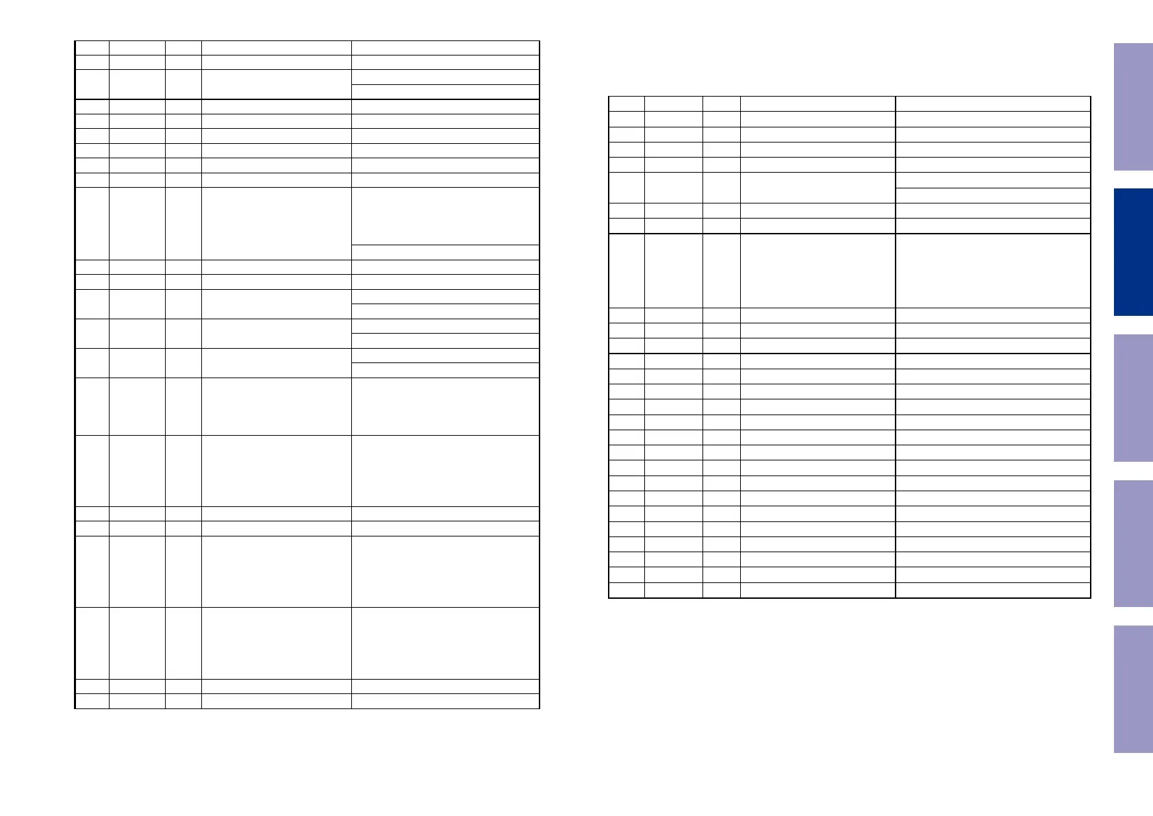
78 GP19 B General Purpose IO 19 SPI1 MISO
79 GP20 B General Purpose IO 20 SPI1 MOSI
80 GP21 B General Purpose IO 21
External Interrupt 3
SPI2 CS
Audio serial data for external DAC
82 IOVDD33 P I/O Power supply (3.3V)
83 IOVSS33 P I/O Ground
84 DMCK O Master clock for external DAC
85 DBCK O Audio serial data Bit clock
86 DLRCK O Audio serial data frame clock
87 GP22 B General Purpose IO 22
Chip Select 2
When GP22 is used for CS2, the external
pull-up resistor (48 kΩ) has to be connected
with this pin
External Interrupt 4
88 GP23 B General Purpose IO 23 HUART1 DI
89 GP24 B General Purpose IO 24 HUART1 DO
90 GP25 B General Purpose IO 25
SPI2 CK
91 GP26 B General Purpose IO 26
External Interrupt 6
SPI2 MISO
92 GP27 B General Purpose IO 27
External Interrupt 7
SPI2 MOSI
93 GP28 B General Purpose IO 28
Wake-UP
When GP28 is used for WAKE-UP signal
input pin, the external pull-down resistor
(48kΩ) has to be connected with this pin.
94 TDI B
JTAG TDI input
When GP43is used for TDI of
JTAG, the external pull-up resistor
(48kΩ) has to be connected with
this pin.
General Purpose IO 43
95 VDD12 P Digital power supply (1.2V)
96 VSS12 P Digital Ground
97 TDO B
JTAG TDO Output
When GP44 is used for TDO of
JTAG, the external pull-up resistor
(48kΩ) has to be connected with
this pin.
General Purpose IO 44
98 TMS B
JTAG TMS input
When GP45 is used for TMS of
JTAG, the external pull-up resistor
(48kΩ) has to be connected with
this pin.
General Purpose IO 45
99 TCK I JTAG Clock Input
100 GP29 B General Purpose IO 29 CDDSP SCOR0
101 GP30 B General Purpose IO 30 CDDSP BCLK0
102 GP31 B General Purpose IO 31 CDDSP DATA0
103 GP32 B General Purpose IO 32 CDDSP LRCK0
104 GP33 B General Purpose IO 33 SBDT0
106 GP35 B General Purpose IO 35
Timer0 Output
External Interrupt 10
107 GP36 B General Purpose IO 36 External UCLK
108 RESETN I System Reset
109 NTRST I
JTAG NRST Input
When NTRSR is used for Reset of
JTAG, the external pull-up resistor
(48kΩ) has to be connected with
this pin.
110 IOVSS33 P I/O Ground
111 TEST I Test
112 XI I System clock input
113 XO O System clock output
115 IOVSS33 P I/O Ground
116 USBVDD33 P USB Power supply (3.3V)
117 USBDP B USB D+
118 USBDM B USB D-
119 USBVSS33 P USB Ground (3.3V)
120 PLL3VSS12 P PLL3 Ground (1.2V)
121 PLL3VDD12 P PLL3 Power supply (1.2V)
122 PLL2VSS12 P PLL2 Ground (1.2V)
123 PLL2VDD12 P PLL2 Power supply (1.2V)
124 PLL1VSS12 P PLL1 Ground (1.2V)
125 PLL1VDD12 P PLL1 Power supply (1.2V)
126 ADIN4 I ADC analog input[4]
127 ADIN3 I ADC analog input[3]
Note: Pin type ‘D’ means open drain output
Before Servicing
This Unit
Electrical Mechanical Repair Information Updating
45
 Loading...