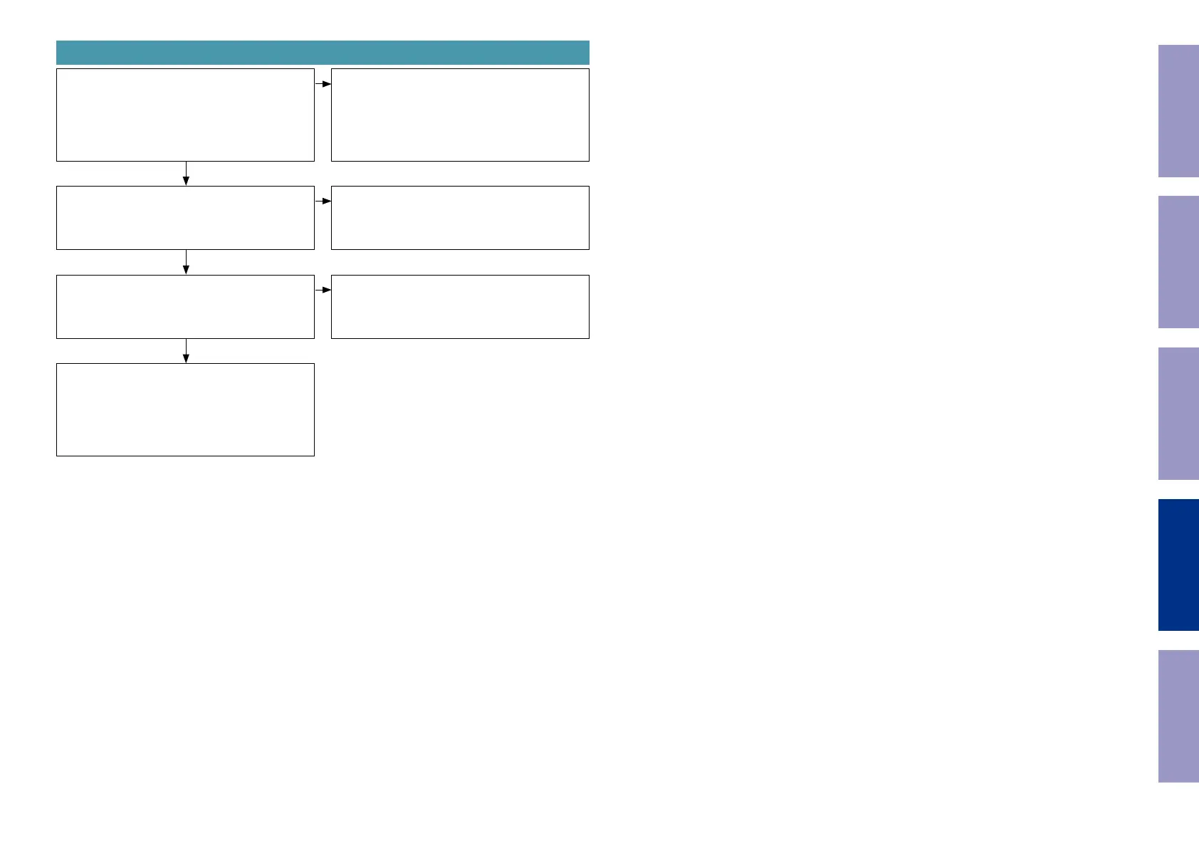
7. No audio from headphones.
Check the audio output status as follows
MAIN PCB
Check the circuit from [U24: 10, 12pin] to DIS-
PLAY PCB [XP3: 2, 3pin].
Check the output of [U19 : STA339BW].
MAIN PCB
[U19 : 17, 18, 19, 20pin]
PWM output is normal.
Check the Detection circuit of Headphone.
MAIN PCB
[U10 : 40pin]
[U10: 40pin] changes from Lo to Hi when head-
phones are connected to this unit
Check the output of [U24 : SGM4917].
MAIN PCB
[U24 : 10, 12pin]
Audio output is normal.
Check the following parts and surrounding
circuits
MAIN PCB
[U19]
Check the status of the headphone detection
circuit as follows
Check the circuit from MAIN PCB [U10 : 40pin] to
DISPLAY PCB [XP3 : 5, 8pin].
Check the following parts and surrounding
circuits
MAIN PCB
[U24]
NO
NO
NO
YES
YES
YES
Before Servicing
This Unit
Electrical Mechanical Repair Information Updating
44
 Loading...