Do you have a question about the Denon DAP-5500 and is the answer not in the manual?
Guidance on placement and cable management to prevent audio/video interference.
Crucial safety advice regarding plug usage and voltage selection.
Detailed technical parameters for the analog audio inputs and outputs.
Technical parameters for digital audio interface, DAC conversion, and filters.
Specifications for additional functions and overall power, dimensions, and weight.
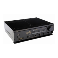
Identification of front panel controls and indicators with numerical references.
Step-by-step instructions for disassembling the unit by section.
Diagrams and instructions for connecting external audio components.
Important precautions to ensure safe and proper audio component connections.
A high-level functional overview of the audio signal path and processing blocks.
Detailed steps for calibrating internal audio circuits using test equipment.
Detailed schematic showing the internal architecture of the digital audio processing unit.
Waveform diagrams illustrating digital data timing and signal synchronization.
Procedure for calibrating the sampling frequency indication on the unit.
Identification and pinouts for various integrated circuits used in the unit.
Identification and pinouts for transistors, diodes, and optocouplers.
Component layout and part numbers for the digital signal processing board.
Component layout and part numbers for the digital power supply board.
Component layout and part numbers for the digital/analog input board.
Component layout and part numbers for the analog power supply board.
Component layout and part numbers for the servo control unit board.
Visual representation of the unit's physical assembly with numbered parts.
A comprehensive list of parts corresponding to the exploded view diagram.
List of items included with the unit for packing and accessories.
Supplementary list of parts, potentially for different model variations.
Diagram illustrating the interconnections between internal circuit boards and components.
Detailed circuit schematic for the analog processing sections of the unit.
Detailed circuit schematic for the digital signal processing sections of the unit.
Essential safety information regarding specific component replacements and leakage current testing.