Do you have a question about the Denon DCD-735 and is the answer not in the manual?
| Type | CD Player |
|---|---|
| Disc format | CD, CD-R, CD-RW |
| Frequency response | 2 Hz - 20 kHz |
| Dynamic range | 100 dB |
| Total harmonic distortion | 0.002% |
| Digital converter | 24-bit/192kHz |
| Digital outputs | Optical, Coaxial |
| Output | 2.0V |
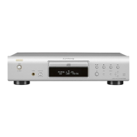
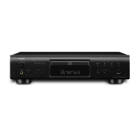
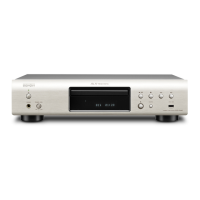
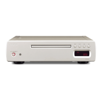
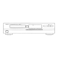
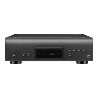
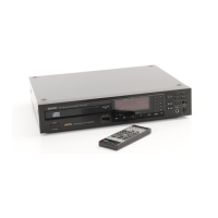
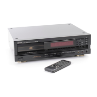
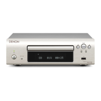
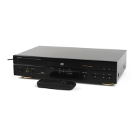
Diagrams and labels for front, rear, and remote control units.
Critical safety warnings and important usage guidelines.
Highlights advanced audio tech, digital filter, servo system, and convenience.
Explains power, disc handling, listening controls, display, and sensor.
Covers play, pause, stop, search, programming, and track selection.
Details Auto Space, Time Mode, and Dimmer functions.
How to play specific tracks or programmed sequences.
Details repeat playback and manual search operations.
How to set up playback using an external timer.
Inserting batteries, directions for use, and operational notes.
Advice on placement and cable management to avoid interference.
Lists common problems, solutions, and technical details.
Step-by-step guide to remove loader panel and top cover.
Instructions for detaching the front and rear panels.
Procedure to enter the service mode for servo checks.
Details button functions within the service program.
Lists required equipment and procedure for tracking offset check.
Steps to confirm focus and tracking gain automatic adjustment values.
Procedures for checking Focus BIAS, EF BALANCE, and HF level.
Steps to perform the heat run test and understand error messages.
Criteria for deciding if a pick-up needs replacement.
Steps to diagnose focus search issues and potential causes.
Procedure to measure VFE, clean lens, and identify PU issues.
Steps to measure VTE, clean lens, and identify PU issues.
Procedure to measure VHF, clean lens, and identify PU issues.
Detailed pin configuration and function for BA6392FP IC.
Pinouts for µPC4570C, PCM61P-L, SM5845AF.
Pinouts for TC74HCU04AP and SBX1910.
Visual identification of common transistors used in the unit.
Visual identification of common diodes used in the unit.
Explains how to interpret resistor and capacitor part number codes.
Diagrams showing component placement on mechanism boards.
Diagram showing major chassis parts and their assembly.
List of parts for the CD mechanism unit and included accessories.
Exploded view of the CD mechanism unit components.
Exploded view of the optical pick-up unit components.
Diagram showing connections between mechanism, main board, and other units.
Schematic of the digital servo and signal processing section.
Schematic of main board and display unit circuits.
Schematic of headphone jack and power supply circuits.