M
Michelle MorrisonAug 15, 2025
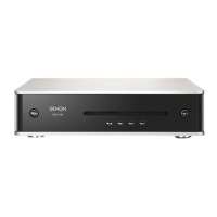
Why is there no sound or distorted sound from my Denon DCD-720AE?
- HHolly RobinsonAug 15, 2025
If you're not getting any sound or the sound is distorted from your Denon CD Player, there could be a couple of things to check: * Make sure the output cables are properly connected to the amplifier. Check the connections to ensure they are secure. * Verify that the amplifier's function settings and controls are correctly adjusted.