EasyManua.ls Logo

Denon DCM-360 Service Manual

Denon DCM-360
35 pages
To Next Page IconTo Next Page
Page #1 background imageLoading...
Page #1 background image
DENO
SERVICE
MANUAL
moveEL
DCM-360/260
STEREO
CD
PLAYER
i
—TABLE
OF
CONTENTS—
SPECIFICATIONS
-
+
+
ce
tt
es
EG)
BiB
SEs
ONG
ja
Fee
a
ee
ee
es
a
ae er
o)
OPERATING
INSTRUCTIONS
i
at
oa,
RE
ga
ae
a
ee
ee
ee
3~9
NOTE
FOR
‘HANDLING
Ait
LASER
PICK-UP
+t
ee
eu
ee
ee
ee
S
Sree
Seam
eg
Spake
o
10,11
DISASSEMBLY
--
°° os
eee tee
(Roe
ee
SAS
ek
ee
a
ee
ee
ae
12°
ADJUSTMENT
«eet
et
es
Be
ehea
ong.
Ara
eh
a
ea
Bs
eee
a
er
eee
1
HEAT
RUN
MODE
FUNCTION
_
6
Bee
we
oe
7
eae
aes
CR
ee
Re
een
a
ee
ee
Kee
ee
17
_
SEMICONDUCTORS
--
+--+
se:
Daa
32
Ge
ag
de
tant
a
Maid,
beens)
sige
oe
als
eeu
2
+
+
+
18~28
NOTE
ON
PARTS
LIST
-
ee
a
Le
eee
6
2G
PARTS
uST
‘OF
P.W.BOARD
= © 5 6
ft
ee
bata
ussstor
quer
Gi
espe:
°e
s+
30~39
~PARTS
LIST
OF
MECHANISM
UNIT
-
+
+
°
=
i
i
Pe
hae?
aes
eee
Bok
ots
~
40
EXPLODED
VIEW
OF
MECHANISM
UNIT
--
>
-
+--+
+
St
Re
ee
41
PARTS
LIST
OF
EXPLODED
VIEW
--
+--+:
----
es
we
ai
Be
tee
ieee
soa
sas
Gee
1.42
PARTS
LIST
OF
PACKING&ACCESSORIES
we
eae
Te
ea
iet
ede
Bs
Banas
1a
aoa
gE
ah
Sete
nee
Shes
42
EXPLODED
VIEW
-----:
3°:
Pee
RES
es
a
ee
tees
8
+
43
P.W.BOARD
See
RS
te,
a
ea
ee
ee
Fb
ee
es
‘)
ee
7
Ca
Bie
BBE
Beta
44~46
WIRING
DIAGRAM
«ce
ce
ee
ee
Pier
Rees
heche
a
re
on
eee
ee
47
SCHEMATIC
DIAGRAM
a
a
Sr
48~51
Hi-Fi.
Stereo
cD
Player
Question and Answer IconNeed help?

Do you have a question about the Denon DCM-360 and is the answer not in the manual?

Denon DCM-360 Specifications

General IconGeneral
BrandDenon
ModelDCM-360
CategoryCD Player
LanguageEnglish

Summary

Specifications

Audio Specifications

Details audio performance metrics like frequency response, SNR, and distortion.

Functions and Display

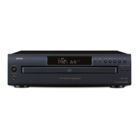
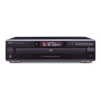
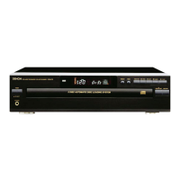
Lists player functions, display elements, and remote control features.

Overall Specifications

Covers power supply, consumption, dimensions, and weight.

Remote Control Unit RC-258

Provides specifications for the remote control unit.

Important Safety Instructions

General Safety Warnings

Crucial safety precautions to prevent fire, electric shock, and damage.

Installation Precautions

Guidance on proper placement and environmental conditions for safe operation.

Notes on Use and Observations

Handling Precautions

Guidelines for handling the unit, power cord, and preventing damage.

Installation and Environmental Notes

Advice on placement to avoid interference and ensure proper ventilation.

Compact Disc Handling

Instructions for proper handling and care of compact discs.

Key Player Features

Highlights key features like ALPHA Processor and A.M.N.S. technology.

Parts and Functions Overview

Front Panel Controls and Indicators

Describes the purpose and operation of each button on the front panel.

Rear Panel and Connections

Identifies rear panel connections and output terminals.

Display Window Information

Explains the information displayed on the unit's display window.

Disc Loading and Basic Playback

Drawer Operation and Disc Loading

Step-by-step guide on opening/closing the drawer and inserting discs.

Normal Playback Procedure

Detailed steps for standard playback of a CD.

Audio Output Connections

Guide for connecting the CD player to an amplifier or audio system.

Advanced Playback Modes

Direct Track and Disc Selection

How to select specific discs and tracks directly.

Disc Skipping During Playback

Method to change discs during playback using the SKIP button.

Track Programming and Playback

Steps for creating custom playback sequences with programmed tracks.

Repeat and Random Playback Options

Explains repeat and random playback functions.

Track Navigation and Playback Control

Automatic and Manual Track Search

Using search functions to find specific points within a track.

Temporary Stop (Pause) Function

How to pause playback and resume from the same point.

Cueing for Practice

Using direct selection and pause for vocal practice with music.

Remote Control Operation Guide

Inserting Dry Battery

Instructions for installing batteries in the remote control unit.

Remote Control Functions

How to use the remote control for various player functions.

Remote Control Cautions

Important notes regarding remote control operation and safety.

Troubleshooting Common Issues

Common issues and their solutions for player operation.

Laser Pick-up Handling and Safety

Laser Pick-up Component Description

Overview of the laser pick-up assembly components.

Pick-up Handling and Storage

Guidelines for safe handling, storage, and transport of the pick-up.

Laser Diode (LD) Safety Precautions

Warnings and precautions related to the laser diode and eye safety.

2-Axis Actuator Handling

Notes on handling the actuator to avoid magnetic interference or dust.

Disassembly and Servo System

Unit Disassembly Instructions

Steps for disassembling the CD player unit, including covers.

Activating the Service Program

Procedure to enter and activate the unit's service program mode.

Service Program Operation

How to use buttons during service program actuation for adjustments.

Digital Servo Adjustment Procedures

Required Equipment for Adjustment

Lists necessary tools and discs for servo adjustment.

Adjustment Point Locations

Identifies specific test points on the main unit for adjustment.

Confirming Servo Adjustment Values

How to check and confirm digital servo adjustment values against a table.

Error Message Interpretation

Explains how to interpret error messages displayed during servo adjustment.

RF Level Confirmation

Oscilloscope Connection and Setup

How to connect an oscilloscope for RF level checking.

Waveform Quality Check

Procedure to check the RF level and confirm waveform quality.

Semiconductor Component Details

IC HD6433723079F Pinout and Functions

Detailed pin assignments and functions for IC300.

IC HD6433723079F Terminal Functions

Lists terminal names, symbols, I/O, and specific functions.

Integrated Circuit Functions

IC MN662720RB Terminal Functions

Details pin assignments and functions for IC102.

IC AN8805SB Terminal Functions

Lists pin assignments and functions for IC100.

Component Pin Assignments and Functions

IC AN8805SB Terminal Functions

Provides pin details and functions for IC100.

IC AN8389S Terminal Functions

Lists pin assignments and functions for IC101.

IC Terminal Function Details

IC AN8389S Terminal Functions

Details pin functions, voltage, and circuit diagrams for AN8389S.

AN8389S Terminal Function Circuitry

Continuation of AN8389S pin details including power and ground terminals.

Additional Component Details

PCM1710U Terminal Function

Pin assignments and functions for the PCM1710U DAC chip.

SM5848-AF Terminal Function

Details pin functions and block diagram for the SM5848-AF digital filter.

Component Identification and Specifications

Transistors and Diodes Identification

Lists common transistors and diodes with their pinouts and types.

Resistor and Capacitor Specifications

Explains resistor/capacitor identification codes and specifications.

Notes for Ordering Parts

Guidance on ordering parts, availability, and marking conventions.

Main Printed Wiring Board Parts List (DCM-360)

Semiconductors Group

Lists semiconductor components used on the DCM-360 main PCB.

Resistors Group

Lists resistors used on the DCM-360 main PCB.

Capacitors Group

Lists capacitors used on the DCM-360 main PCB.

Main Printed Wiring Board Parts List (DCM-360 Continued)

Capacitors Group (Continued)

Continues the list of capacitors for the DCM-360 main PCB.

Other Parts Group

Lists other miscellaneous parts for the DCM-360.

Main Printed Wiring Board Parts List (DCM-260)

Semiconductors Group

Lists semiconductor components for the DCM-260 main PCB.

Resistors Group

Lists resistors for the DCM-260 main PCB.

Capacitors Group

Lists capacitors for the DCM-260 main PCB.

Main Printed Wiring Board Parts List (DCM-260 Continued)

Capacitors Group (Continued)

Continues the capacitor list for the DCM-260 main PCB.

Other Parts Group

Lists other components for the DCM-260.

Front Unit Assembly Parts List (DCM-260)

Semiconductors Group

Lists semiconductors for the DCM-260 front unit.

Resistors Group

Lists resistors for the DCM-260 front unit.

Capacitors Group

Lists capacitors for the DCM-260 front unit.

Other Parts Group

Lists other parts for the DCM-260 front unit.

CD Mechanism Parts and Exploded View

CD Mechanism Unit Parts List (TCD-77S)

Lists individual parts of the TCD-77S CD mechanism unit.

Exploded View of CD Mechanism Unit

Visual representation of the CD mechanism unit with numbered parts.

Chassis and Cabinet Parts List

Chassis and Cabinet Components

Lists parts related to the player's chassis, cabinet, and internal structure.

Packing and Accessories List

Lists items included in the product packaging and accessories.

Chassis and Cabinet Exploded View

Chassis and Cabinet Components Diagram

Visual diagram showing assembly of the chassis and cabinet parts.

Critical Parts Safety Warning

Critical safety notice regarding replacement parts with critical characteristics.

Printed Wiring Board - Main Unit (DCM-360)

Component Layout Diagram

Diagram showing the placement of components on the DCM-360 main PWB.

Printed Wiring Board - Main Unit (DCM-260)

Component Layout Diagram

Diagram showing the placement of components on the DCM-260 main PWB.

Display Printed Wiring Board

Component Layout Diagram

Diagram showing component placement on the display PWB.

Wiring Diagram Overview

System Block Diagram

High-level overview of the CD player's internal signal flow and connections.

Main Unit Wiring Details

Wiring details for the main unit and its key interface blocks.

Schematic Diagram - 1/4 (DCM-360/260)

Main Block Schematic Representation

Detailed schematic of the main processing blocks and their interconnections.

Power Supply and Key Sections Schematic

Schematic for power supply and key control circuits.

Schematic Diagram - 1/4 (Continued)

Display and Headphone Circuitry Schematic

Detailed schematic of the display and headphone output circuits.

Schematic Notes and Symbols

Important notes regarding schematic conventions, component values, and warnings.

Schematic Diagram - 3/4 (DCM-360)

Main Block Schematic (DCM-360)

Detailed schematic of major functional blocks within the DCM-360.

Power Supply and Control Circuitry (DCM-360)

Schematic details for power regulation and control functions.

Schematic Diagram - 4/4 (DCM-260)

Main Block Schematic (DCM-260)

Detailed schematic of major functional blocks within the DCM-260.

Power Supply and Control Circuitry (DCM-260)

Schematic details for power regulation and control functions.

Related product manuals