Explanatory Photos for“ DISASSEMBLY”
• The angles from which the photos are taken are shown by “Photo angle: A, B, C, D“ .
• See the diagram below about the shooting direction of each photograph.
• Photographs with no shooting direction indicated were taken from the top of the set.
The viewpoint of each photograph
(Shooting direction)
[View from the front]
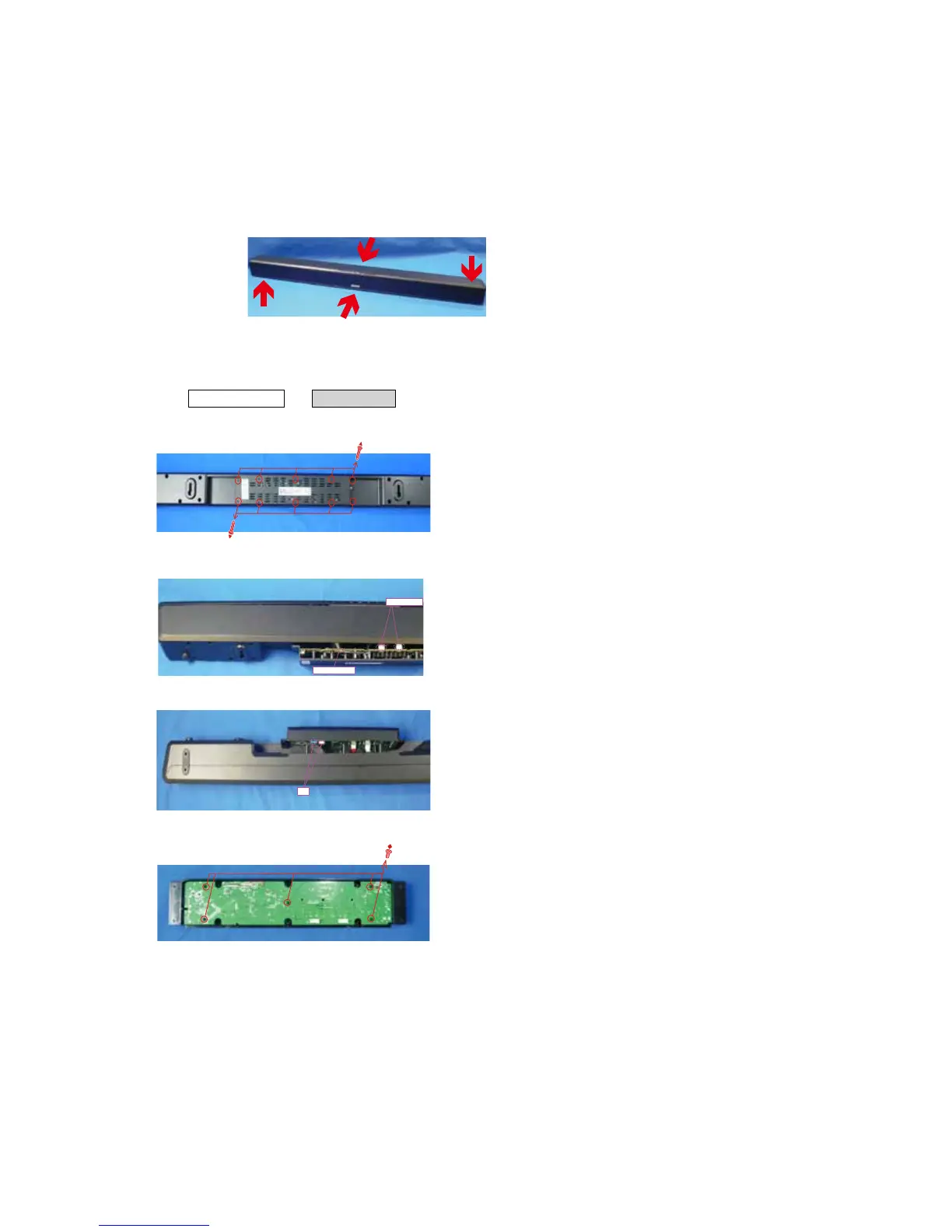
1. MAIN PWB ASSY
Proceeding : REAR PANEL
→
MAIN PWB
(1) Remove the screws.
Shooting direction B (Rear side)
(2) Remove the connector wires and remove the antenna connector.
Shooting direction D (Top side)
(3) Remove the FFCs.
Shooting direction C (Bottom side)
(4) Remove the screws.
 Loading...