I
6. Tape guide height verification
Set the jig board THG-801 on the mechanical unit. Adjust it by
turning the verification adjustment nut
@ so that the 3.8
mm part on the jig stick THG-801 jig shaft move without con-
tacting the tape guide part of the tape guide
@.
7. Verifying fast-forwarding torque
Load a cassette-type torque meter and verify that the reading on
the torque meter at the median value is 30-80 g-cm during
playback.
If the reading is outside the standard, verify the voltage of the
reel motor (3.3 V ±0.3 V). If the voltage is low the torque isweak
and when the voltage is high the torque isstrong .
Also verify the reel thrusting gutter in Item 8.
8. Verification Reel Driver Thrust Movement
Verify that the thrust movement is 3.0 to 4.0 mm.
9. FF and REW Torque Verification
o When using cassette-type torque meter:
Verify that the readings at the end of the fast-forward and
rewind is 80-160 g-cm.
o Load the cassette half-modified jig and hook the tip of a dial
tension meter (fu!1scale 100-300 g) on the triangle part.
Switch to the FF (REW) position and feed a tape at a some-
what slower pace than the speed of the tape that is rolled in.
Verify that the value on the dial tension meter at that time is
more than 80 g-cm.
10. Back tension torque verification for
recording/playback
Load a cassette-type torque meter to verify that the reading on
the torque meter for recording/playback is 6 to 16 g-cm and
there is no unevenness.
If the reading is outside the standard values, verify the reel thrust
gutter or replace the spring(D
11. FF and REW Time Verification
Load a DENON HD-7E/60 cassette tape and verify that the FF
and REW time is 80 to 110 seconds. If the reading is outside the
standard values, verify Items 8 and 10.
12. Accidental erasure prevention, metal and
chrome switch function verification
Verify that switch @is functioning normally depending on
whether the hole is present or not.
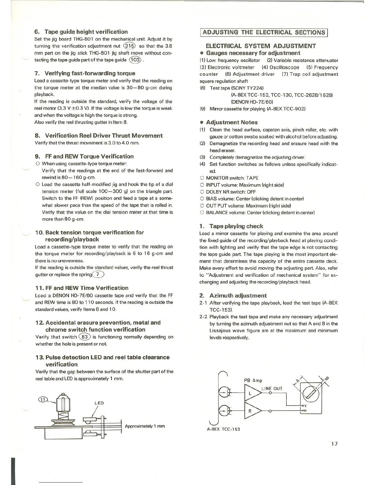
13. Pulse detection LED and reel table clearance
verification
Verify that the gap between the surface of the shutter part of the
reel table and LEDis approximately 1 mm.
LED
I
~ .,,,,.om,"'Y 1mm
I ADJUSTING THE ELECTRICAL SECTIONS I
ELECTRICAL SYSTEM ADJUSTMENT
a Gauges necessary for adjustment
(1) Low frequency oscillator (2) Variable resistance attenuator
(3) Electronic voltmeter (4) Oscilloscope (5) Frequency
counter (6) Adjustment driver (7) Trap coil adjustment
square regulation shaft
(8) Test tape (SONY TY224)
(A-BEX TCC-153, TCC-130, TCC-262B/162B)
(DENON'HD-7E/60)
(9) Mirror cassette for playing (A-BEX TCC-902)
• Adjustment Notes
(1) Clean the head surface, capstan axis. pinch roller, etc. with
gauze or cotton swabs soaked with alcohol before adjusting.
(2) Demagnetize the recording head and erasure head with the
head eraser.
(3) Completely demagnetize the adjusting driver.
(4) Set function switches as follows unless specifically indicat-
ed.
o MONITOR switch: TAPE
o INPUT volume: Maximum (right side)
o DOLBY NR switch: OFF
o BIAS volume: Center (clicking detent in center)
o OUT PUT volume: Maximum (right side)
o BALANCE volume: Center (clicking detent in center)
1. Tape playing check
Load a mirror cassette for playing and examine the area around
the fixed guide of the recording/playback head at playing condi-
tion with lighting and verify that the tape edge is not contacting
the tape guide part. The tape playing is the most important ele-
ment that determines the capacity of the entire cassette deck.
Make every effort to avoid moving the adjusting part. Also, refer
to "Adjustment and verification of mechanical system" for ex-
changing and adjusting the recording/playback head.
2. Azimuth adjustment
2-1 After verifying the tape playback, load the test tape (A-BEX
TCC-153).
2-2 Playback the test tape and make any necessary adjustment
by turning the azimuth adjustment nut so that A and B in the
Lissajous wave figure are at the maximum and minimum
levels respectively.
A-BEX TCC-153
17
 Loading...