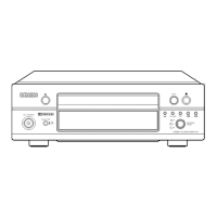
NAMES AND FUNCTIONS OF PARTS
o 0008
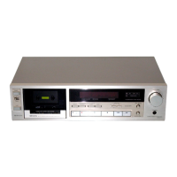
DEtJON PRECISION AUOIO COMPONENT/STdAEO CJ.SSETTE TAPE DECK DRM-600A rD~;"';;T~'M
CERAMIC COMPOSITE CASSETTE STABILIZER
YIBRATION ABSORBING foIECH ••••NISM
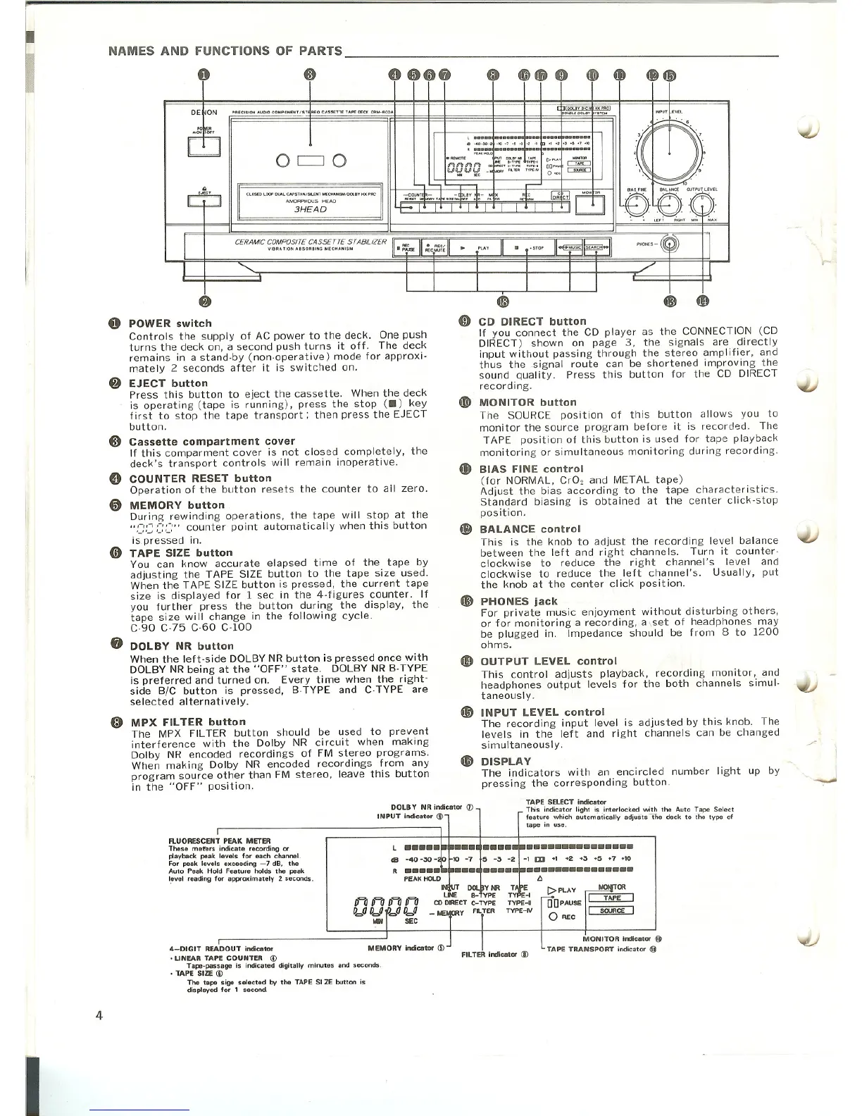
POWER switch
Controls the supply of AC power to the deck. One push
turns the deck on, a second push turns it off. The deck
remains in a stand·by (non-operative) mode for approxi·
mately 2 seconds after it is switched on.
EJECT button
Press this button to eject the cassette. When the deck
is operating (tape is running), press the stop (.) key
first to stop the tape transport; then press the EJECT
button.
Cassette compartment cover
If this comparment cover is not closed completely, the
deck's transport controls will remain inoperative.
COUNTER RESET button
Operation of the button resets the counter to all zero.
MEMORY button
During rewinding operations, the tape will stop at the
":~:C:C::~,'" counter point automatically when this button
is pressed in.
TAPE SIZE button
You can know accurate elapsed time of the tape by
adjusting the TAPE SIZE button to the tape size used.
When the TAPE SIZE button is pressed, the current tape
size is displayed for 1 sec in the 4-figures counter _ If
you further press the button during the display, the
tape size will change in the following cycle.
C·90 C·75 C-60 C·100
DOLBY NR button
When the left·side DOLBY NR button is pressed once with
DOLBY NR being at the "OFF" state. DOLBY NR B·TYPE
is preferred and turned on. Every time when the right·
side
BIC button is pressed, B·TYPE and C-TYPE are
selected alternatively.
«;) MPX FILTER button
The MPX FILTER button should be used to prevent
interference with the Dolby NR circuit when making
Dolby NR encoded recordings of FM stereo programs.
When making Dolby NR encoded recordings from any
program source other than FM stereo, leave this button
in the "OFF" position.
---
, · .. ··I·· .... ·I···F.·.. I....···
CO_40.J,Q_t -10-7-5-3-2 _1 ., _2"_5·7'10
R ••••• a•••••••••••••••••••••
CD DIRECT button
If you connect the CD player as the CONNECTION (CD
DIRECT) shown on page 3, the signals are directly
input without passing through the stereo amplifier, and
thus the signal route can be shortened improving the
sound quality. Press this button for the CD DIRECT
recording.
MONITOR button
The SOURCE position of this button allows you to
monitor the source program before it is record8d. The
TAPE position of this button is used for tape playback
monitoring or simultaneous monitoring during recording.
BIAS FINE control
(for NORMAL, Cr02 and METAL tape)
Adjust the bias according to the tape characteristics.
Standard biasing is obtained at the center click-stop
position.
BALANCE control
This is the knob to adjust the recording level balance
between the left and right channels. Turn it counter-
clockwise to reduce the right channel's level and
clockwise to reduce the left channel's. Usually, put
the knob at the center click position.
PHONES jack
For private music enjoyment without disturbing others,
or for monitoring a recording, a,set of headphones may
be plugged in. Impedance should be from
8 to 1200
ohms.
OUTPUT LEVEL control
This control adjusts playback, recording monitor, and
headphones output levels for the both channels simul·
taneous Iy.
f!i) INPUT LEVEL control
The recording input level is adjusted by this knob. The
levels in the left and right channels can be changed
simultaneously.
~ DISPLAY
The indicators with an encircled number light up by
pressing the corresponding button.
~T 0:::;;- 1'~~_1
DQDQ _£~'c,.:;:; ;;;:;.
3HEAD
OCJO
J:1~~~F
o
o
•••••••••••••••
TAPE SELECT indicator
This indicator light is.interlocked with the Auto Tape Select
feature which autcmatically adjusts -the deck to the type of
tape in use.
-1
m +1 +2 +3 +5 +7 +10
•••••••••••••••
t:.
[> PLAY
00PAUSE
o 'lEC
_OR
TAPE
SOURCE
MONITOR indicator @
TAPE TRANSPORT indicator @
FI LTER indicator (j)
III
R
DOLBY NR indicator (1)
INPUT indicator ())
4-DIGIT READOUT indicator
• LINEAR TAPE COUNTER @
Tape-passage is indicated digitally minutes and seconds .
• TAPE SIZE (I)
The tape sige selected by the TAPE 51ZE button is
displayed for 1 second.
flUORESCENT PEAK METER
These mefers indicate recording or
playback peak levels for each channel.
For peak levels exceeding
-7 dB, the
Auto Peak Hold Feature holds the peak
I!"vel reading for approximately 2 seconds.
4
I